Centrifugal separator having oil coating on sidewalls
a centrifugal separator and sidewall technology, applied in centrifuges, crankcase ventilation, machines/engines, etc., can solve the problems of unreliable and inefficient separation, oil contamination of cleaned gas, etc., and achieve the effect of avoiding or reducing sticky agglomerations
- Summary
- Abstract
- Description
- Claims
- Application Information
AI Technical Summary
Benefits of technology
Problems solved by technology
Method used
Image
Examples
first embodiment
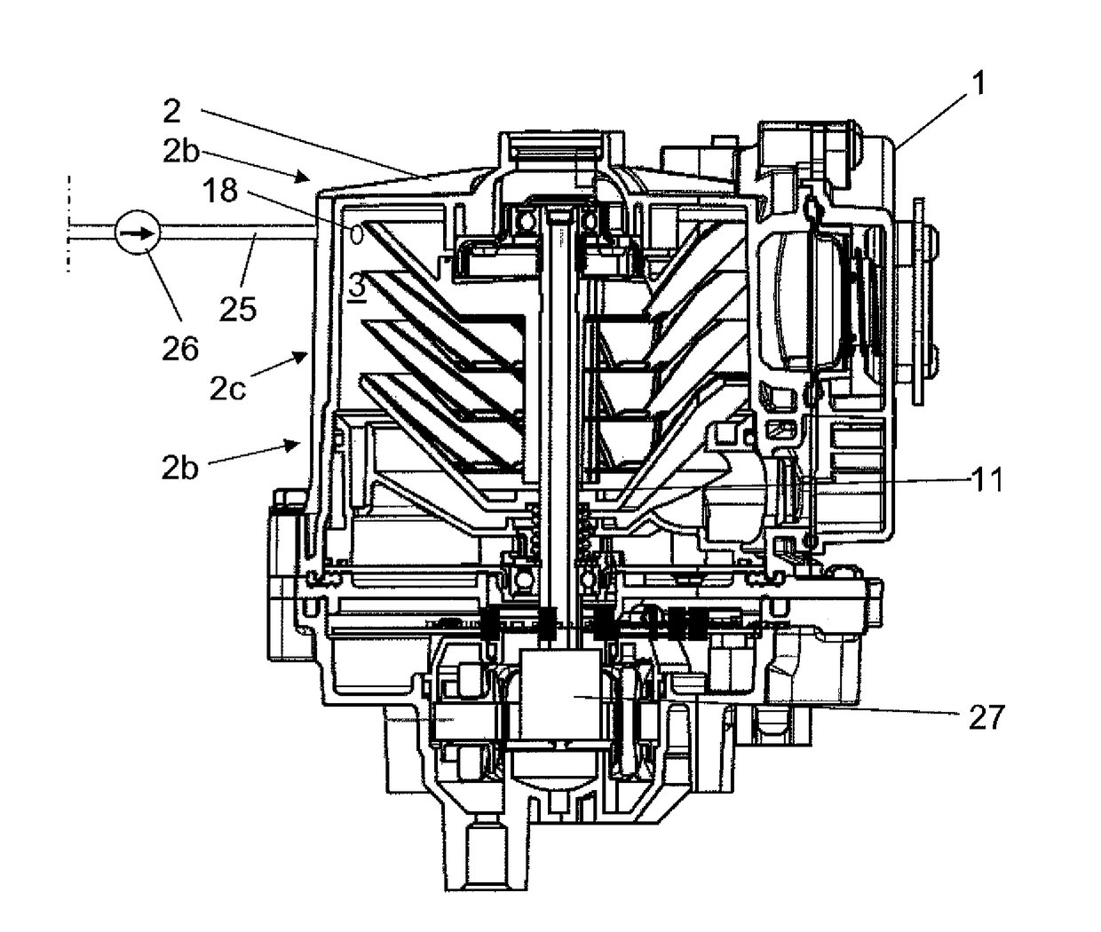
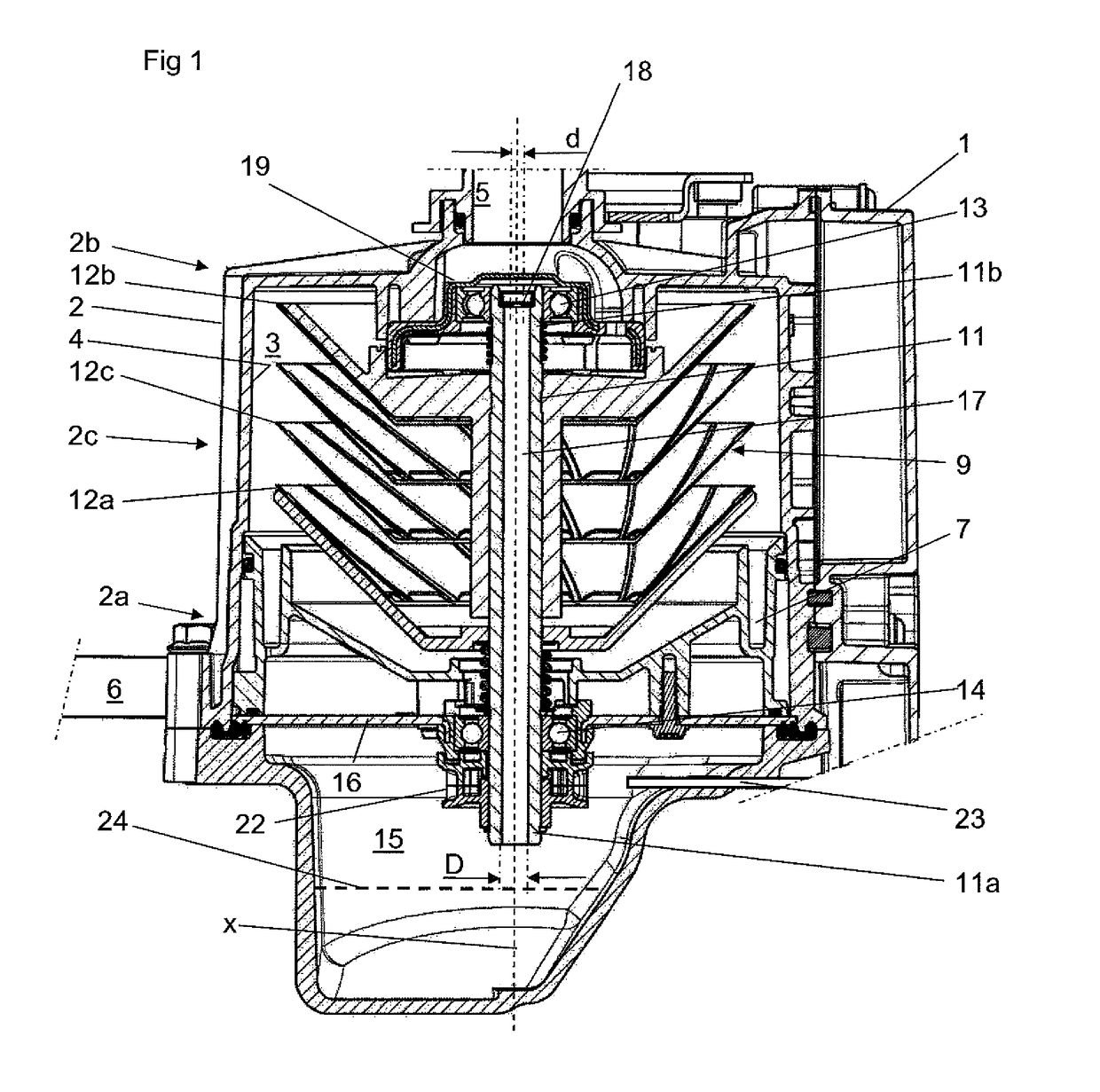
[0030]FIG. 1 discloses a centrifugal separator for cleaning a gas containing oil, such a crankcase gases from an internal combustion engine (not disclosed). FIG. 1 also discloses a pressure control valve 1 designed to keep the pressure within a safe range in the crankcase of the internal combustion engine.
[0031]The centrifugal separator comprises a stationary casing 2 defining a separation space 3 within the stationary casing 2. The stationary casing 2 is stationary in relation to the internal combustion engine 1. The stationary casing 2 comprises a first end portion 2a, an opposite second end portion 2b, and an intermediate portion 2c provided between and adjoining the first end portion 2a and the second end portion 2b. In the embodiments disclosed, the first end portion 2a forms a lower portion during operation of the centrifugal separator, whereas the second end portion 2b forms an upper portion.
[0032]The stationary casing 2 has an inner wall surface 4 facing the separation space...
third embodiment
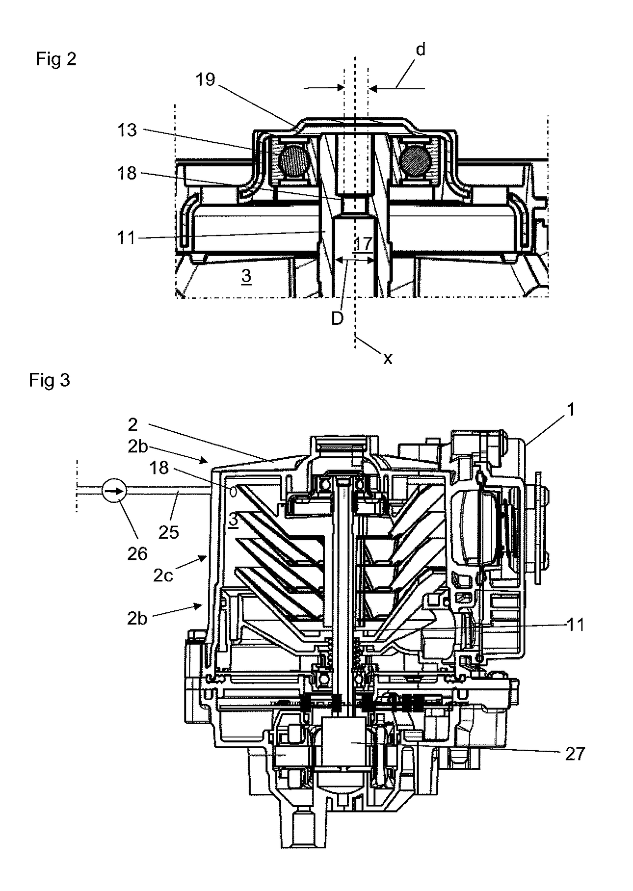
[0052]In the third embodiment, the aperture diameter of the inlet nozzle 18 is 0.3 to 1.5 mm, preferably, 0.4 to 1.0 mm, for instance 0.5 mm. The oil may then be supplied to the inlet nozzle 18 at a pressure of 3-6 bars.
[0053]Furthermore, in the third embodiment, the drive member is replaced by and comprises a separate motor, e.g. an electrical motor 27, connected to the spindle 11 for rotating the spindle 11 and the centrifuge rotor 9. The separate motor may alternatively comprise a separate pneumatic motor or a separate hydraulic motor. The spindle 11 and the centrifuge rotor 9 may also be driven by means of the crankshaft of the internal combustion engine.
PUM
 Abstract
Description
Claims
Application Information
 - R&D
- Intellectual Property
- Life Sciences
- Materials
- Tech Scout
- Unparalleled Data Quality
- Higher Quality Content
- 60% Fewer Hallucinations
Browse by: Latest US Patents, China's latest patents, Technical Efficacy Thesaurus, Application Domain, Technology Topic, Popular Technical Reports.
© 2025 PatSnap. All rights reserved.Legal|Privacy policy|Modern Slavery Act Transparency Statement|Sitemap|About US| Contact US: help@patsnap.com


