Robot control device, robot, and robot system

a robot and control device technology, applied in the direction of programmed manipulators, programme control, instruments, etc., can solve the problem of difficult to attenuate the vibration of the robot arm, and achieve the effect of suppressing the vibration of the first robot arm

Active Publication Date: 2015-04-30
SEIKO EPSON CORP
View PDF9 Cites 25 Cited by
  • Summary
  • Abstract
  • Description
  • Claims
  • Application Information

AI Technical Summary

Benefits of technology

[0009]An advantage of some aspects of the invention is to provide a robot control device, a robot, and a robot system that can suppress the vibration of a first robot arm, a second robot arm, and a trunk.

Problems solved by technology

Since it is difficult for the hand to perform the work of gripping a workpiece while the hand is vibrating, it is necessary to wait for the vibration of the hand to stop.
Accordingly, the double-arm robots as mentioned above has a problem in that it is difficult to attenuate the vibration of the robot arm because the vibration of the trunk is transmitted to the robot arms even if the vibration of the robot arms is attenuated using the method described in JP-A-2005-242794.

Method used


Image

  • Robot control device, robot, and robot system
  • Robot control device, robot, and robot system
  • Robot control device, robot, and robot system

Examples


Embodiment Construction

[0059]Hereinafter, a robot control device, a robot, and a robot system according to the invention will be described in detail with reference to preferred embodiments illustrated in the accompanying drawings.

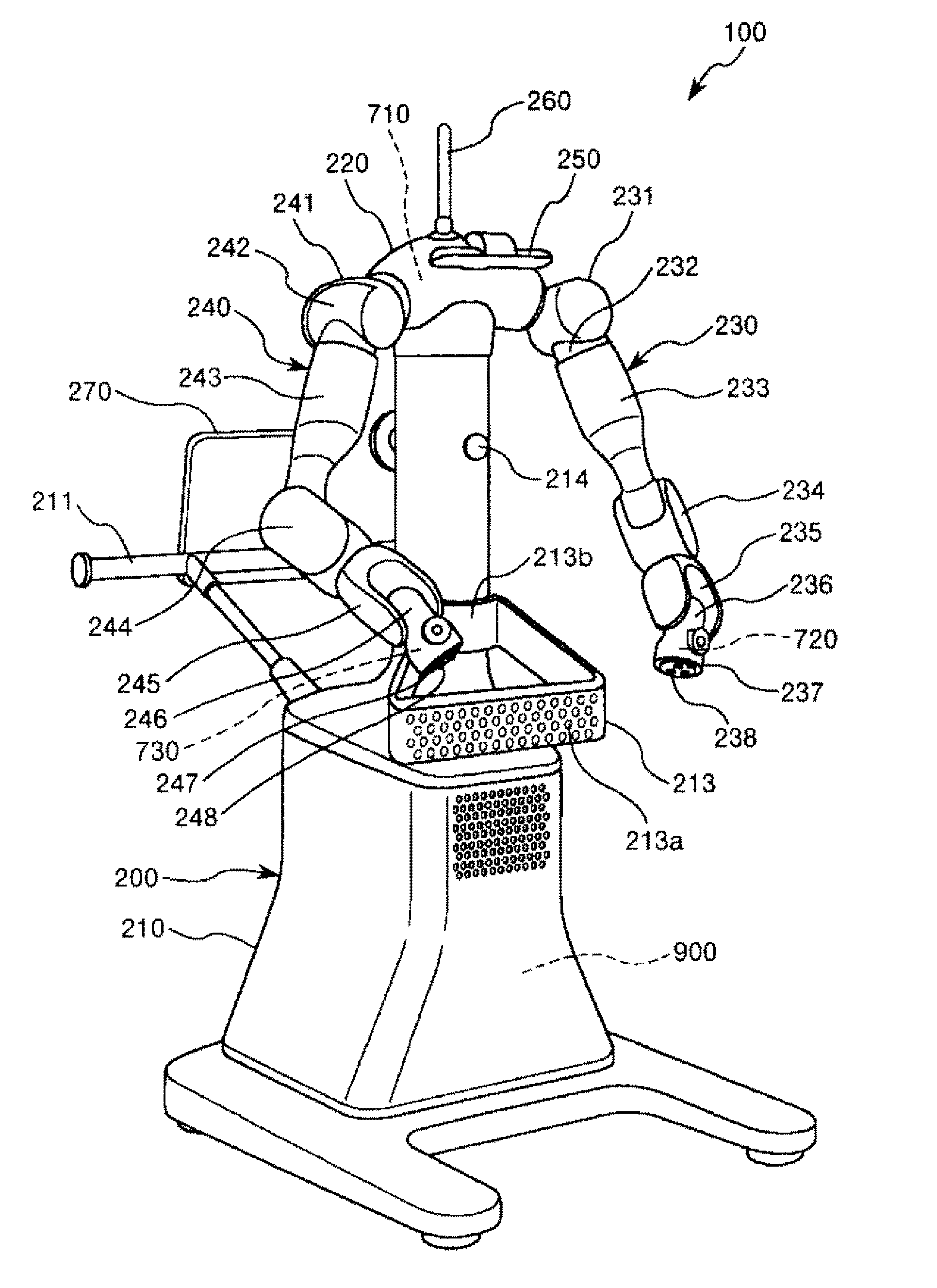
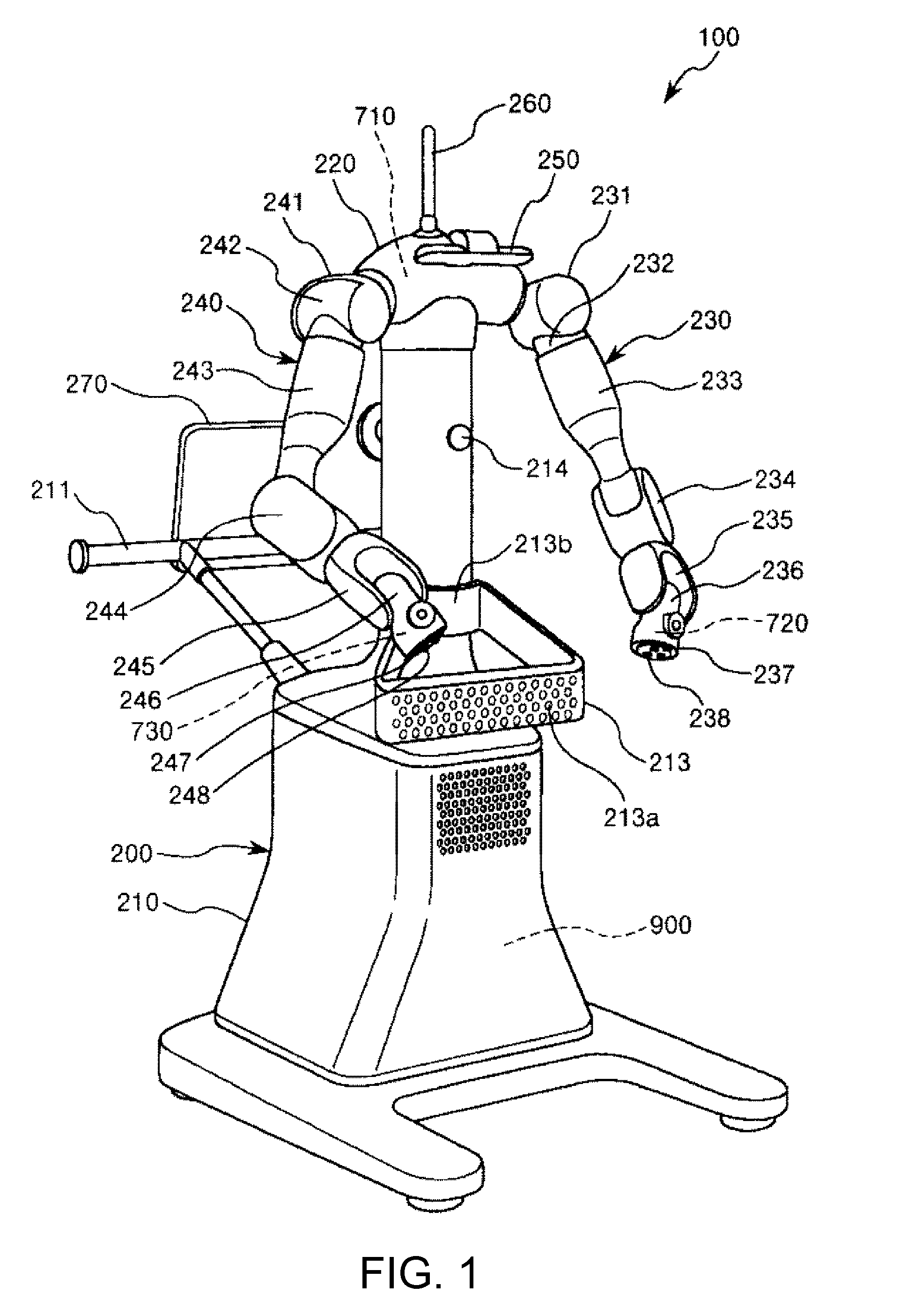
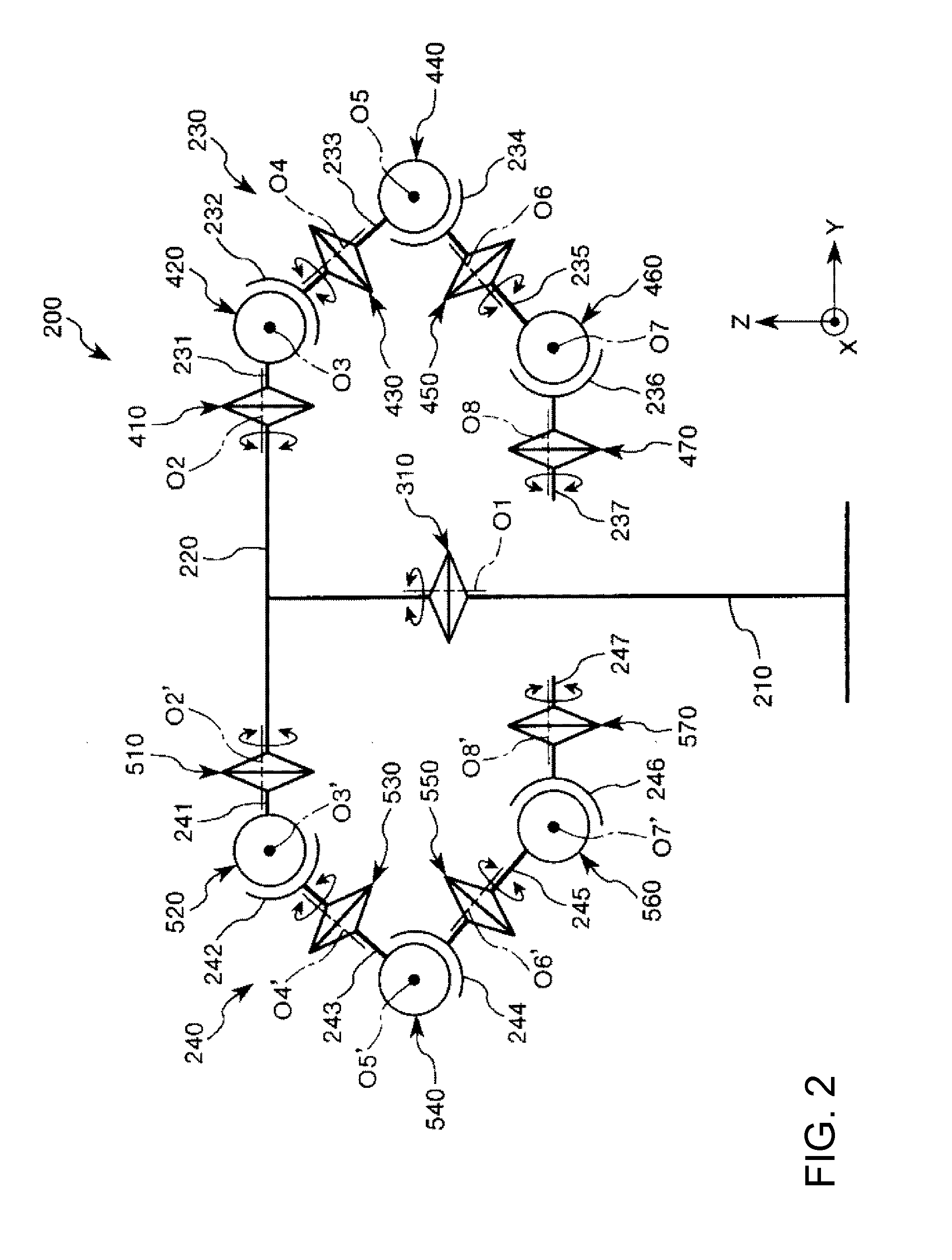
[0060]FIG. 1 is a perspective view illustrating an embodiment of the robot system according to the invention. FIG. 2 is a schematic view showing rotational axes of the robot of the robot system illustrated in FIG. 1. FIG. 3 is a view illustrating the positions of end effectors to be mounted on the robot of the robot system illustrated in FIG. 1. FIG. 4 is a block diagram illustrating a control system of the robot of the robot system illustrated in FIG. 1. FIGS. 5 to 7 are block diagrams illustrating the drive control of the robot of the robot system illustrated in FIG. 1, respectively. FIGS. 8 and 9 are respectively views for explaining the measurement conditions of the angular velocity of the robot of the robot system illustrated in FIG. 1. FIG. 10, FIG. 11, and FIGS. 13 to 16 a...


PUM


Abstract

A robot control device controls the operation of a robot including a trunk that is rotatable around an axis, first and second robot arms that are provided at the trunk and rotatable with respect to the trunk, and first, second, and third inertial sensors. In an operation in which the second robot arm is brought into a stationary state and the first robot arm is rotated around the axis from the stationary state and moved to a target position, the robot control device makes B / A<0.27 satisfied when a maximum value of the amplitude of the angular velocity of the trunk around the axis before the first robot arm reaches the target position is defined as A, and a maximum value of the amplitude of the angular velocity of the trunk around the axis after the first robot arm has reached the target position first is defined as B.

Description

BACKGROUND[0001]1. Technical Field[0002]The present invention relates to a robot control device, a robot, and a robot system.[0003]2. Related Art[0004]Robots having a robot arm constituted by links of multiple joints are known. For example a hand or the like as an end effector is mounted on a tip portion of the robot arm. The robots are utilized for a number of apparatuses, such as assembling apparatuses.[0005]In such robots, the robot arm vibrates when the robot arm is moved and stopped. While the robot arm is vibrating, the hand mounted on the tip portion of the robot arm also vibrates. Since it is difficult for the hand to perform the work of gripping a workpiece while the hand is vibrating, it is necessary to wait for the vibration of the hand to stop.[0006]Thus, a method of shortening the time taken for the hand to vibrate in order to raise the productivity of a robot is disclosed in JP-A-2005-242794. Although the robot disclosed in JP-A-2005-242794 is a scalar robot having a b...

Claims


Application Information

Patent Timeline
Patent Type & Authority Applications(United States)
IPC IPC(8): B25J9/16
CPCB25J9/1602Y10S901/09B25J9/1628B25J9/1682B25J5/007B25J9/0087B25J9/162B25J13/088B25J15/0052B25J18/04G05B2219/39109G05B2219/43203
Inventor GOMI, AKIHIROMOTOYOSHI, MASAKI
Owner SEIKO EPSON CORP
Why Eureka
Try Eureka