
Windshield wiper system

Active Publication Date: 2015-05-07
AIRBUS HELICOPTERS DEUT GMBH
View PDF14 Cites 1 Cited by
  • Summary
  • Abstract
  • Description
  • Claims
  • Application Information

AI Technical Summary

Benefits of technology

This patent is for a windshield wiper system for vehicles, specifically for rotary wing aircrafts. The system has improved cleaning performance. It allows for the wiper blade to rotate in a way that is tangential to the windshield, and can be easily installed on different windshields with different levels of curvature. The system can be easily modified to existing wiper systems without needing to change the design.

Problems solved by technology

Due to strong curvatures of modern windshields, particularly the strong curvatures of windshields of rotary wing aircrafts, the cleaning performance of wiper blades is not continuous in all windshield areas.
Especially towards the outer left or outer right side position the windshields of nowadays helicopters are strongly curved which leads to a poor cleaning performance in this area by using conventional wiper systems.
Lean angles α higher than 20° lead to very poor cleaning performance and moreover the frame holding the lip of the wiper blade touches the windshield and subsequently the bias of the lip of the wiper blade against the windshield is restricted.
A further consequence of the frame touching the windshield is that the frame during operation may scratch the windshield.
Different windshields with different degrees of curvature necessitate different special control parts and / or piloting actuators according to said prior art resulting in a high number of different special control parts and / or piloting actuators respectively for small series at relatively high costs.
The additional orientation control of the local angle along the blade is more expensive, heavier and more complex in realization.

Method used


Image

  • Windshield wiper system
  • Windshield wiper system
  • Windshield wiper system

Examples


Embodiment Construction

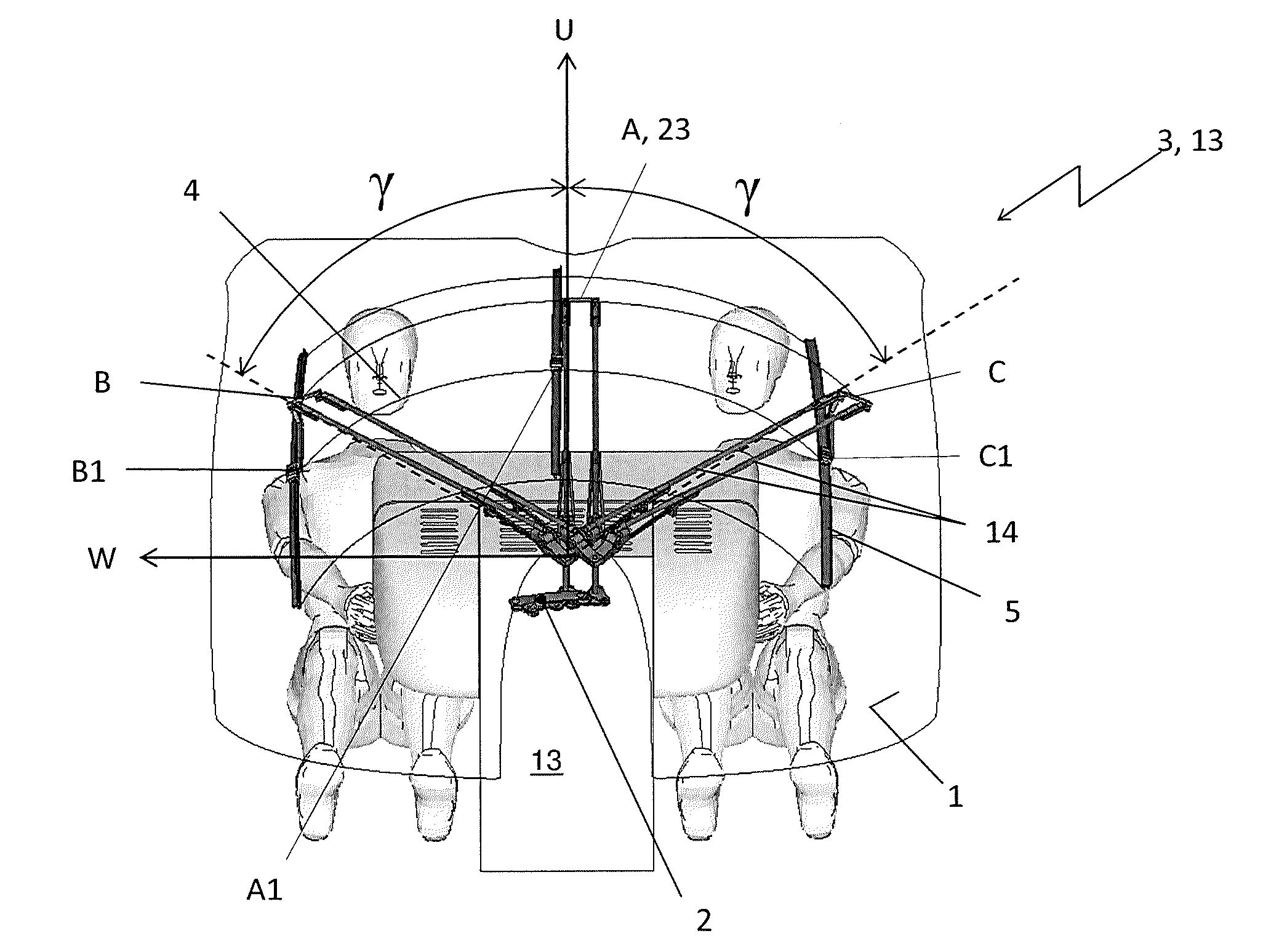
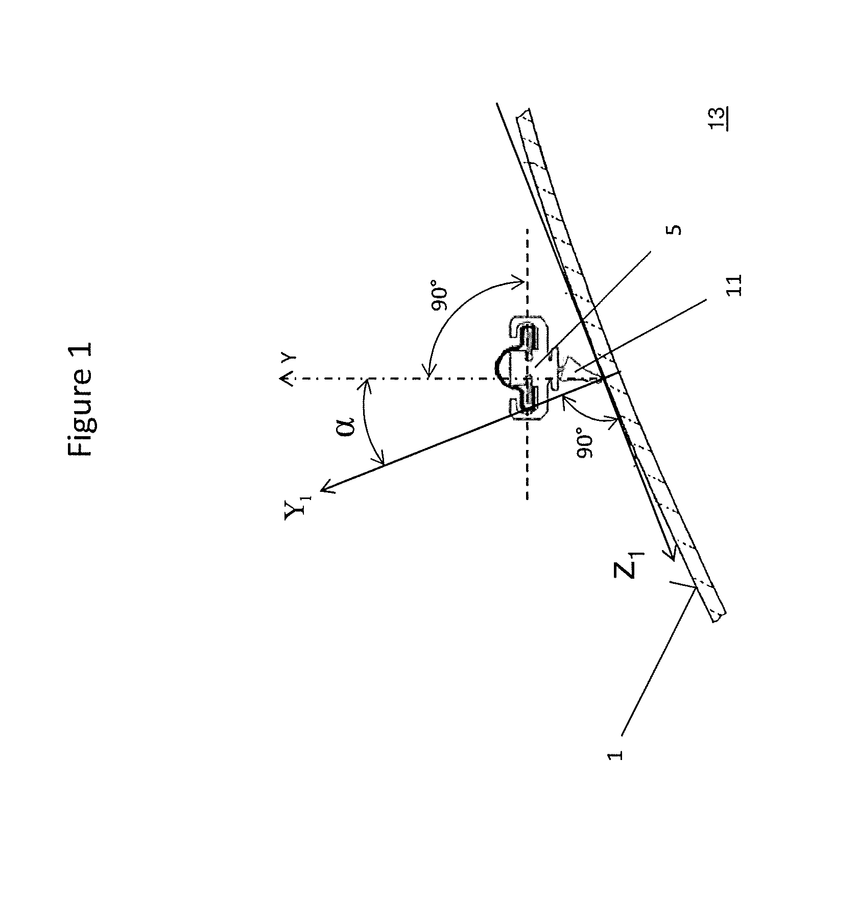
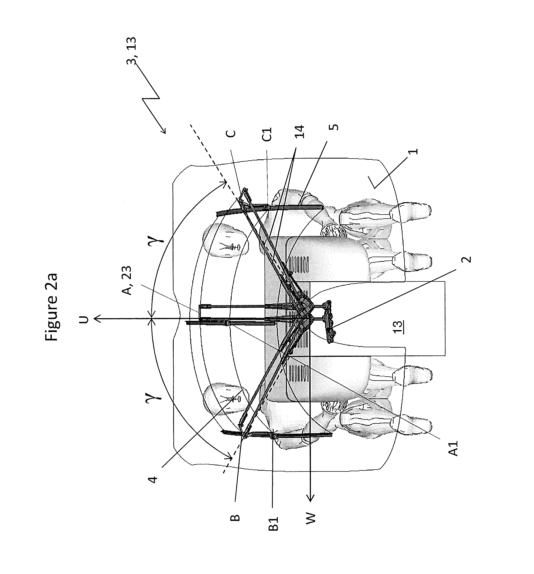
[0028]According to FIG. 1 a vehicle 13 is a rotary wing aircraft, e.g., a helicopter. The vehicle 13 has a windshield surface 1 that is having a strong curved. A windshield wiper system 3 for the outer windshield surface 1 comprises a wiper blade 5 with a wiper blade lip 11 at a contact point on the outer windshield surface 1. A lean angle (α) is defined between a wiper blade axis (Y), which is perpendicular to the longitudinal extension of the wiper blade 5 (l) and is going through the contact point of a lip 11 of the wiper blade 5 with the windshield outer surface 1 and a perpendicular line (Y1) to the windshield outer surface 1 at said same contact point.

[0029]A target lean angle (αT) corresponds to the necessary angle of rotation of the wiper blade 5 about its longitudinal extension (l) to position the wiper blade axis (Y) through said contact point perpendicular to the windshield surface 1, where the lean angle (α) is equal to 0°.

[0030]According to FIG. 2a-c corresponding featu...


PUM


Abstract

A windshield wiper system (3) for vehicles. A windshield (1) has a curved surface. The system (3) comprises two wiper arms (14) and one wiper blade (5), one of said two wiper arms (14) being mounted to said oscillating gear drive (2), said wiper blade (5) being mounted by means of said two wiper arms (14) distal to said oscillating gear drive (2) for oscillation across the windshield (1). Said two wiper arms (14) have each along said curved surface of the windshield (1) a respectively pivotal wiper arm axis (8). At least one cranked fitting (16) and a prolongation fitting (7) are provided, said wiper blade (5) being mounted rotatable about a wiper blade rotation axis (9) by means of said wiper blade holder (21) and said wiper blade fit bolt (22) to said prolongation fitting (7). Said prolongation fitting (7) is mounted rotatable about prolongation fitting rotation axes (18). Said prolongation fitting rotation axes (18) is inclined to said respective wiper arm axis of each of the two wiper arms (14) by an angle 45°<δ<135°.

Description

CROSS REFERENCE TO RELATED APPLICATION[0001]This application claims priority to European patent application No. EP 13 400025.6 filed on Nov. 5, 2013, the disclosure of which is incorporated in its entirety by reference herein.BACKGROUND OF THE INVENTION[0002](1) Field of the Invention[0003]The invention is related to a windshield wiper system for vehicles, particularly a windshield wiper system for rotary wing aircrafts as a helicopter.[0004](2) Description of Related Art[0005]The cleaning performance of wiper blades depends on a lean angle (α) between a wiper blade axis (Y), which is perpendicular to the longitudinal extension of the wiper blade (l) and is going through the contact point of a lip of the wiper blade with the windshield outer surface and a perpendicular line (Y1) to the windshield outer surface at said same contact point.[0006]The best cleaning performance of a wiper blade is provided when the wiper blade is perpendicular to the windshield surface. Due to strong curv...

Claims


Application Information

Patent Timeline
IPC IPC(8): B60S1/34B60S1/44
CPCB60S1/44B60S1/3406B60S1/3409B60S1/42B60S2001/3837B60S1/0452B64C1/1476
Inventor MILLER, VITALILUIK, ROLAND
Owner AIRBUS HELICOPTERS DEUT GMBH
Features
  • Generate Ideas
  • Intellectual Property
  • Life Sciences
  • Materials
  • Tech Scout
  • Unparalleled Data Quality
  • Higher Quality Content
  • 60% Fewer Hallucinations
Learn More