
Image forming apparatus, image forming method and image forming program

Active Publication Date: 2022-01-13
KONICA MINOLTA INC
View PDF0 Cites 0 Cited by
  • Summary
  • Abstract
  • Description
  • Claims
  • Application Information

AI Technical Summary

Benefits of technology

The present invention aims to improve the cleaning performance of a cleaning blade in an image forming apparatus. The apparatus includes an image carrier, a driver, a toner remover, and a hardware processor. The processor evaluates the degree of deterioration of the image carrier or the toner remover and determines the number of times of execution of a removal operation where the image carrier is rotated in a reverse direction and then rotated in the forward direction. The driver is then controlled to execute the removal operation the determined number of times. Overall, this improves the cleaning performance of the image forming apparatus and reduces the amount of residual toner on the image carrier.

Problems solved by technology

Here, paper dust may be bitten between the intermediate transfer belt and the cleaning blade, whereby cleaning failure may occur.

Method used


Image

  • Image forming apparatus, image forming method and image forming program
  • Image forming apparatus, image forming method and image forming program
  • Image forming apparatus, image forming method and image forming program

Examples


Embodiment Construction

[0029]Hereinafter, one or more embodiments of the present invention will be described with reference to the drawings. However, the scope of the invention is not limited to the disclosed embodiments. In the following description, the same components are denoted by the same reference numerals. The names and functions thereof are also the same. Thus, detailed description thereof will not he repeated. Furthermore, in the following description, an MFP will be described as an example of the image forming apparatus. Moreover, in a Multi Function Peripheral (MFP) described below, a recording medium on which an image is to be formed includes a sheet such as a plain sheet, a high quality sheet, a recycled sheet, or a photographic sheet, and an Over Head Projector (OHP) film.

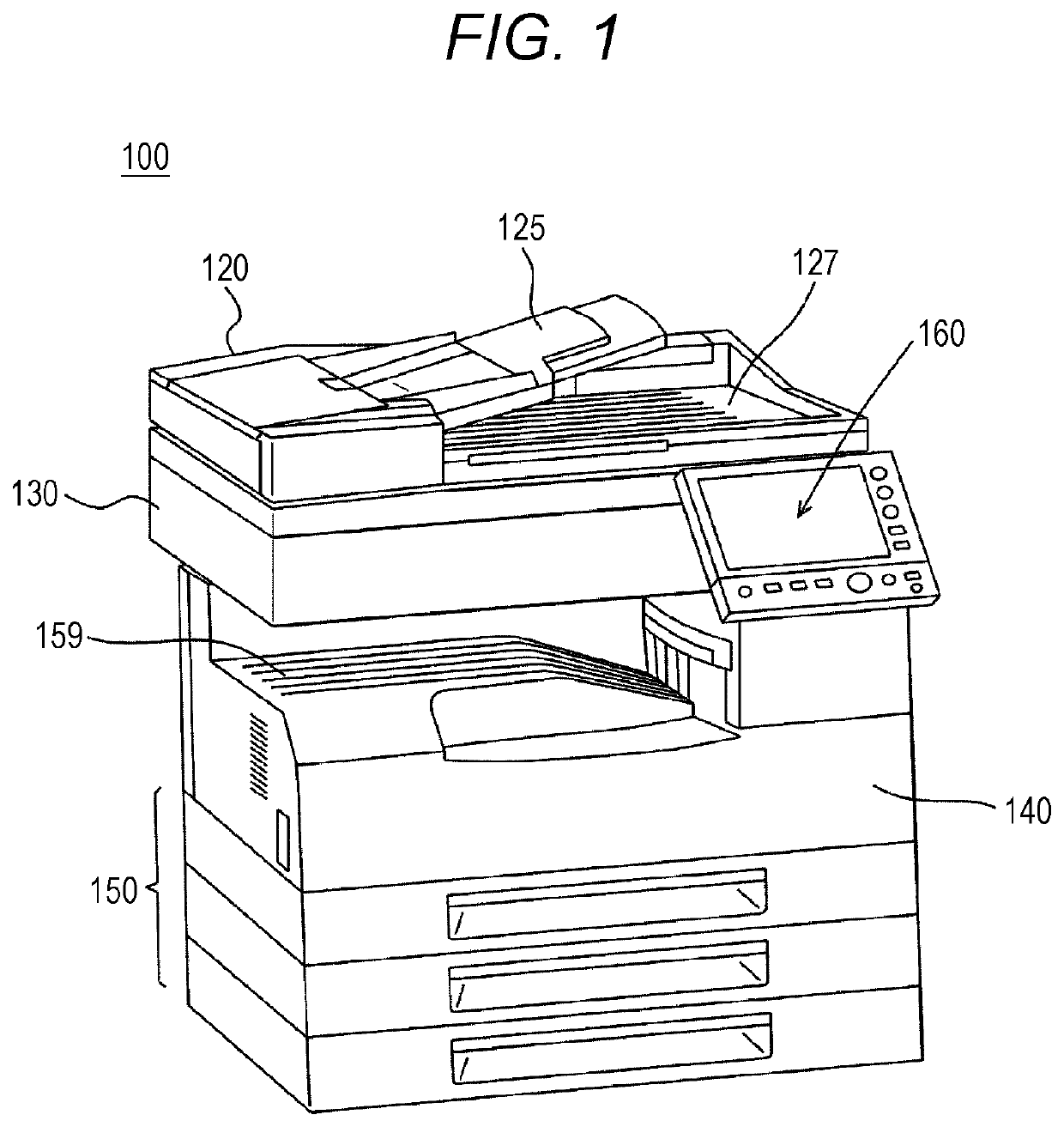
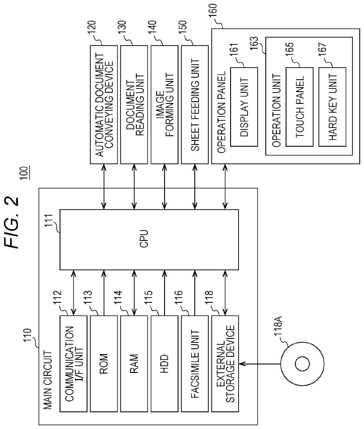
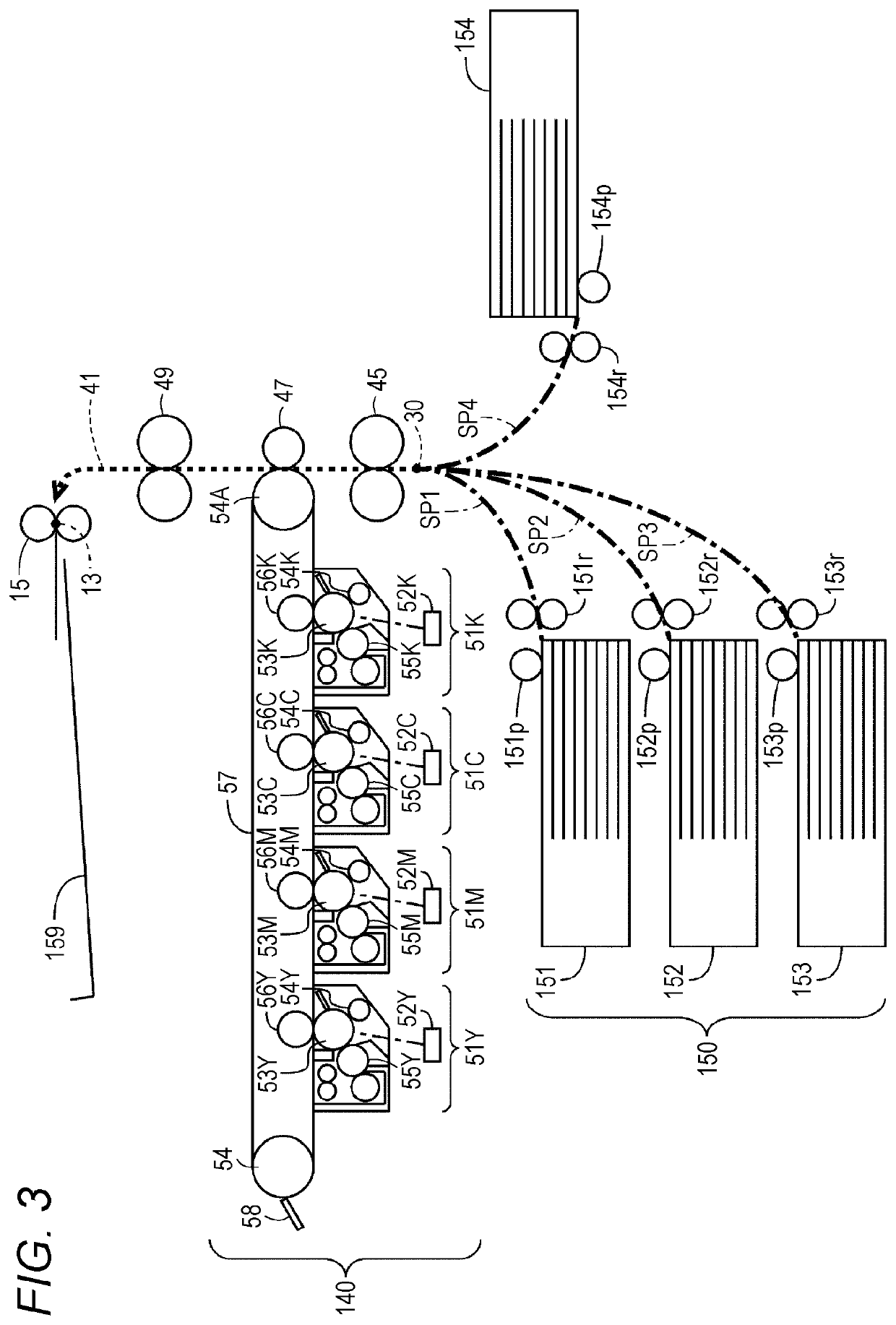
[0030]FIG. 1 is a perspective view illustrating an appearance of the MFP in the present embodiment. FIG. 2 is a block diagram illustrating an outline of a hardware configuration of the MFP. With reference to FIGS. 1 and 2,...


PUM


Abstract

An image forming apparatus includes: an image carrier that carries a toner image including toner; a driver that rotates the image carrier; a toner remover that comes in contact with the image carrier and removes toner remaining on the image carrier while the image carrier is rotated in a forward direction by the driver; and a hardware processor that evaluates a degree of deterioration of the image carrier or the toner remover, determines a number of times of execution of removal operation in which the image carrier is rotated in a reverse direction and then rotated in the forward direction, on the basis of the degree of deterioration, and controls the driver to cause the removal operation to be executed the number of times of execution.

Description

[0001]The entire disclosure of Japanese patent Application No. 2020-120136, filed on Jul. 13, 2020, is incorporated herein by reference in its entirety.BACKGROUNDTechnological Field[0002]The present invention relates to an image forming apparatus, an image funning method and an image forming program, and in particular relates to an image forming apparatus including a cleaning blade provided to be in contact with an intermediate transfer belt, and an image forming method and an image forming program executed by the image forming apparatus.Description of the Related Art[0003]In an intermediate transfer method image forming apparatus, a latent image on a photoreceptor drum is developed, whereby a toner image is formed. The toner image formed on the photoreceptor drum is transferred to an intermediate transfer belt. The toner image transferred to the intermediate transfer belt is further transferred to a recording medium such as a sheet, whereby an image is formed on the recording mediu...

Claims


Application Information

Patent Timeline
IPC IPC(8): G03G15/00G03G21/00
CPCG03G15/50G03G21/0011G03G21/0005G03G21/0076G03G15/16G03G15/553G03G15/161
Inventor KIMURA, MASATO
Owner KONICA MINOLTA INC
Features
  • Generate Ideas
  • Intellectual Property
  • Life Sciences
  • Materials
  • Tech Scout
  • Unparalleled Data Quality
  • Higher Quality Content
  • 60% Fewer Hallucinations
Learn More