Water-stop structure for wire harness

a wire harness and water stop technology, which is applied in the direction of insulated conductors, electric cable installations, cables, etc., can solve the problems of insufficient intimate contact between the middle portion of the water stop tube and the water stop region of the wire harness, and the inability to secure sufficient water stop performance, etc., to achieve small maximum shrinkage percentage, improve water stop performance of the water stop structure, and improve the effect of water stop performan

Inactive Publication Date: 2015-05-07
SUMITOMO WIRING SYST LTD
View PDF5 Cites 9 Cited by
  • Summary
  • Abstract
  • Description
  • Claims
  • Application Information

AI Technical Summary

Benefits of technology

[0007]It is an object of the present invention to provide a water-stop structure, including a water-stop tube, in which the water-stop tube can be brought into intimate contact with a water-stop region of a wire harness having a steep thickness gradient and thus water-stop performance is improved.
[0011]In the above-described aspects, when heated, the outer water-stop tube tightens the inner water-stop tube that is in direct contact with the water-stop region of the wire harness from the outside at the intermediate position in which the gap between the inner water-stop tube and the water-stop region is likely to be formed. Therefore, even if the water-stop region ranging from the first portion to the second portion has a steep thickness gradient, the inner water-stop tube can be brought into intimate contact with the water-stop region. As a result, it is possible to improve water-stop performance of the water-stop structure.
[0012]Moreover, in the second aspect, the inner water-stop tube is divided into the first inner water-stop tube on the thick first portion side and the second inner water-stop tube on the thin second portion side. In this case, the second inner water-stop tube is easily shrunk to a thinner state without the influence of the first inner water-stop tube, which is shrunk to a relatively thick state. Furthermore, the outer water-stop tube tightens the portion ranging from a portion of the first inner water-stop tube to a portion of the second inner water-stop tube from the outside and fills the gap therebetween. As a result, it is possible to improve water-stop performance of the water-stop structure.
[0013]In the third aspect, the first inner water-stop tube is a water-stop tube that has a thickness corresponding to the thickness of the relatively thick first portion to be covered and has a small maximum shrinkage percentage. Generally, a water-stop tube (heat-shrinkable tube) having a small maximum shrinkage percentage is more inexpensive than a water-stop tube having a large maximum shrinkage percentage. Therefore, with the third aspect, it is possible to reduce the cost of the water-stop structure while securing sufficient water-stop performance.

Problems solved by technology

Incidentally, when the water-stop region ranging from the thick portion to the thin portion in the wire harness has a steep thickness gradient, the intermediate portion between both end portions of the water-stop tube may come into insufficiently intimate contact with the water-stop region of the wire harness.
In this case, it is impossible to secure sufficient water-stop performance.

Method used


Image

  • Water-stop structure for wire harness
  • Water-stop structure for wire harness
  • Water-stop structure for wire harness

Examples


first embodiment

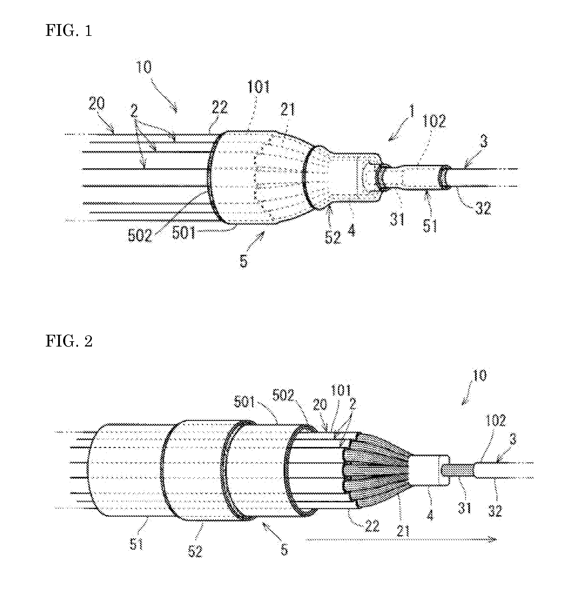
[0020]First, the water-stop structure 1 of a wire harness according to a first embodiment will be described with reference to FIGS. 1 and 2. Hereinafter, the water-stop structure 1 of a wire harness is referred to as “water-stop structure 1” for short.

[0021]As shown in FIGS. 1 and 2, the water-stop structure 1 includes an electric wire bundle 10 with an intermediate joint portion, which is an example of a wire harness, and a water-stop tube group 5. The water-stop tube group 5 includes an inner water-stop tube 51 and an outer water-stop tube 52.

[0022]The electric wire bundle 10 with an intermediate joint portion includes a second electric wire 3 and an electric wire bundle 20 including a plurality of first electric wires 2, and has a structure in which the electric wire bundle 20 and the second electric wire 3 are connected to each other. The first electric wires 2 are insulated electric wires having a linear conductor 21 and an insulating coating 22 that covers the circumference of...

second embodiment

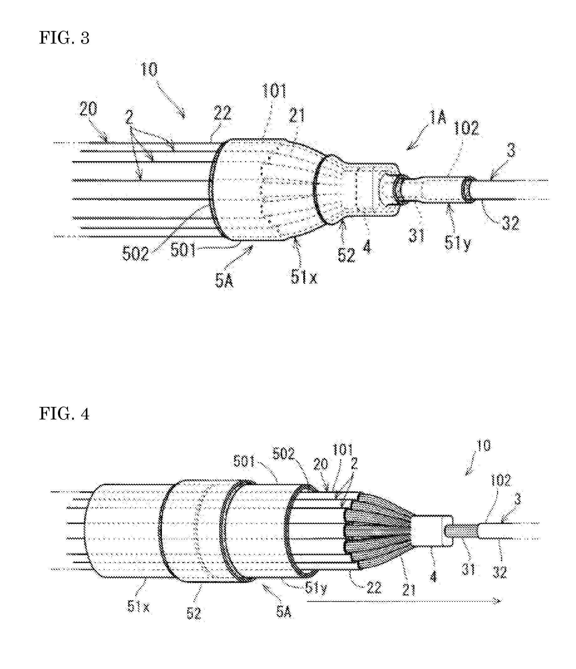
[0037]Next, a water-stop structure 1A of a wire harness according to a second embodiment will be described with reference to FIGS. 3 and 4. Hereinafter, the water-stop structure 1A of a wire harness is referred to as “water-stop structure 1A” for short.

[0038]The water-stop structure 1A has a configuration in which some components are added to the water-stop structure 1 shown in FIG. 1. In FIGS. 3 and 4, the same components as the components shown in FIGS. 1 and 2 are denoted by identical reference numerals. Hereinafter, the difference between the water-stop structure 1A and the water-stop structure 1 will be described.

[0039]As shown in FIGS. 3 and 4, the water-stop structure 1A includes the electric wire bundle 10 with an intermediate joint portion and a water-stop tube group 5A. The water-stop tube group 5A includes a first inner water-stop tube 51x and a second inner water-stop tube 51y, and the outer water-stop tube 52.

[0040]The first inner water-stop tube 51x and the second inne...

application example

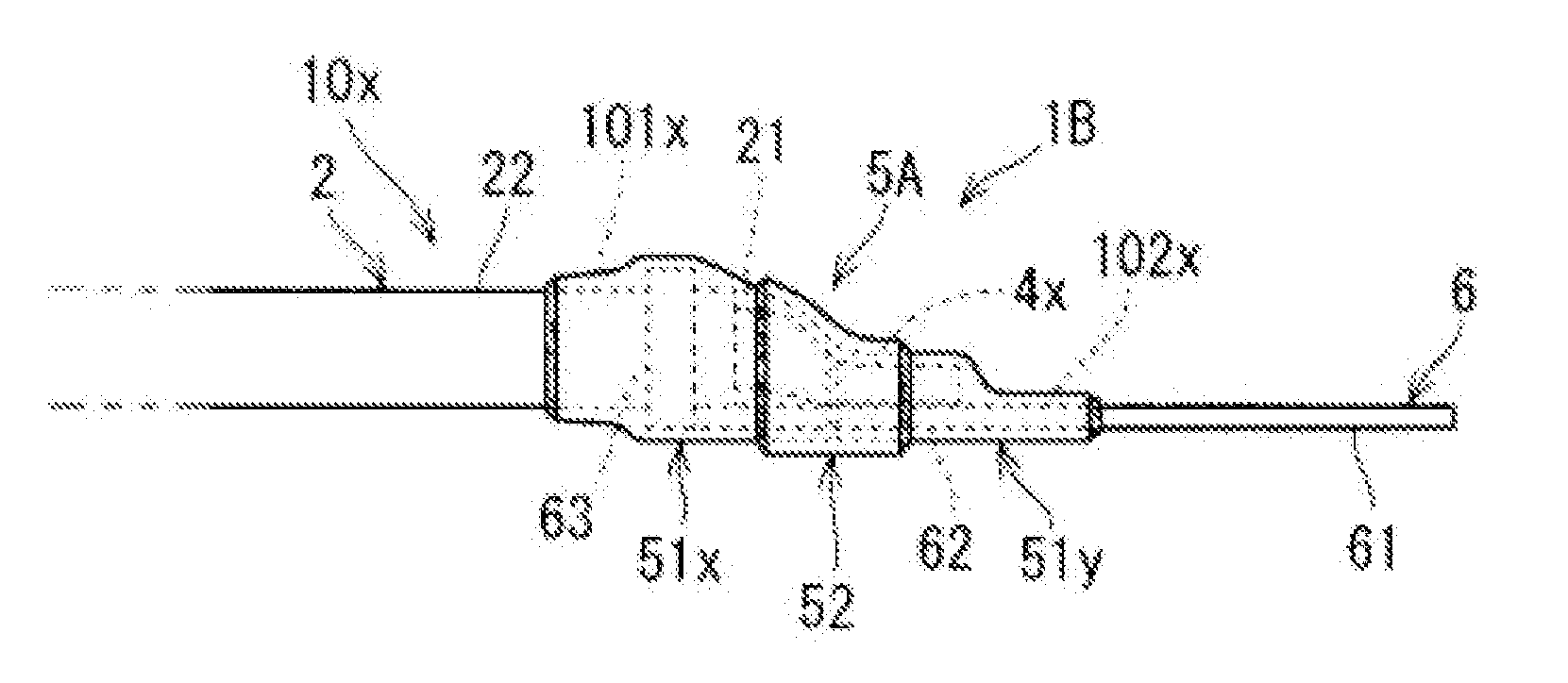
[0047]Next, a water-stop structure 1B of a wire harness according to an application example will be described with reference to FIG. 5. FIG. 5 is a side view of the water-stop structure 1B of a wire harness. Hereinafter, the water-stop structure 1B of a wire harness is referred to as “water-stop structure 1B” for short.

[0048]The water-stop structure 1B differs from the water-stop structure 1A shown in FIG. 3 in that the water-stop structure 1B includes an electric wire 10x with a terminal as a wire harness for which the water-stop tube group 5A stops water. In FIG. 5, the same components as the components shown in FIGS. 1 to 4 are denoted by identical reference numerals. Hereinafter, the difference between the water-stop structure 1B and the water-stop structure 1A will be described.

[0049]The water-stop structure 1B includes the electric wire 10x with a terminal, which is an example of a wire harness, and a water-stop tube group 5A. The water-stop tube group 5A includes the inner wa...


PUM

PropertyMeasurementUnit
water-stop structureaaaaaaaaaa
shrinkage percentageaaaaaaaaaa
heat-shrinkableaaaaaaaaaa

Abstract

A water-stop structure including a water-stop tube is provided in which the water-stop tube can be brought into intimate contact with a water-stop region in a wire harness having a steep thickness gradient and thus water-stop performance is improved. The wire harness includes a first portion and a second portion that is thinner than the first portion. An inner water-stop tube covers the water-stop region ranging from the first portion to the second portion in a state where the inner water-stop tube is heated and shrunk. An outer water-stop tube covers the inner water-stop tube at a position between a portion on the first portion side and a portion on the second portion side in the water-stop region in a state where the outer water-stop tube is heated and shrunk.

Description

TECHNICAL FIELD[0001]The present invention relates to a water-stop structure for a wire harness that stops water with a tube in a water-stop region ranging from a thick portion to a thin portion in the wire harness.BACKGROUND ART[0002]As described in JP 2012-200110A, in a wire harness, a heat-shrinkable water-stop tube sometimes stops water in a water-stop region including a portion in which core wires of insulated electric wires are exposed. The heat-shrinkable water-stop tube has a two-layer structure including a heat-shrinkable tube and a thermoplastic adhesive layer formed on the inner side surface of the heat-shrinkable tube.[0003]The water-stop tube is brought into intimate contact with the water-stop region of the wire harness by a shrinking action of the heat-shrinkable tube and an adhesiveness of the adhesive, and thus high water-stop performance is secured.[0004]Also, the water-stop tube sometimes covers a water-stop region ranging from a thick portion to a thin portion in...

Claims


Application Information

Patent Timeline
Patent Type & Authority Applications(United States)
IPC IPC(8): H01B7/282H01B7/00
CPCH01B7/0045H01B7/2825H01R4/72H02G3/0481H02G15/1806H02G15/046H01R4/70Y02A30/14
Inventor SHIBA, GENHOSHINO, KAZUHIRO
Owner SUMITOMO WIRING SYST LTD
Why Eureka
Try Eureka