Plastic Tube Screen Fills and Fabrication Thereof

a technology of plastic tube and screen, applied in the field of fill media, can solve the problems that the molding method used to fabricate prsf is not applicable to the fabrication of ptsf, and achieve the effects of maximizing heat exchange rate, saving a large amount of pvc materials, and reducing the height of pv

Active Publication Date: 2015-05-07
PARK CHONG MOOK
View PDF24 Cites 4 Cited by
  • Summary
  • Abstract
  • Description
  • Claims
  • Application Information

AI Technical Summary

Benefits of technology

[0043]Another major advantage of the present invention is the ability to save a large amount of PVC materials for fabrication of fill media since the spiral corrugated tube has thin film-like surface and entirely hollow inside of the spiral corrugated tube.
[0044]Yet another major advantage of the present invention is the ability to keep the spiral corrugated tube robust because the corrugated surface of the spiral corrugated tube strengthen the tube body.
[0045]Another major advantage of the present invention is the ability to cool the water much hotter than the warm water able to be cooled by the PTCFs pack because the stack height of the PTSFs packs piled can be extended without loss of their physical integrity or mechanical strength and because they can be of rugged construction with ability to withstand without their damage or loss of shape, since the cooling efficiency of the PTSFs pack has much higher than that of the PVC Fills pack.
[0046]The spiral corrugated tube of the present invention still has other advantages for usage of PTSFs as fill media, which are same with those of PRSFs and described in the previous patent of the present inventor, U.S. patent application Ser. No. 13 / 053,382.

Problems solved by technology

However, the PTSF of the present invention is made with tubes instead of solid rods and the holes in the perforated frame are perfect holes, so that one step injection molding method being used to fabricate PRSF is not applicable to the fabricating of PTSF.

Method used


Image

  • Plastic Tube Screen Fills and Fabrication Thereof
  • Plastic Tube Screen Fills and Fabrication Thereof
  • Plastic Tube Screen Fills and Fabrication Thereof

Examples


Embodiment Construction

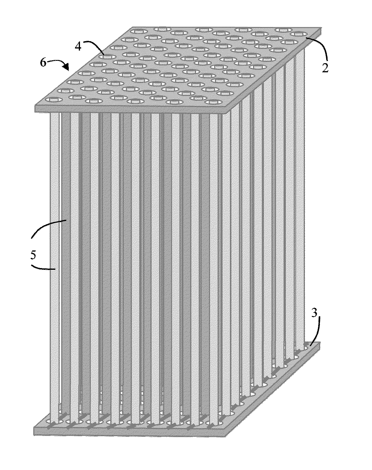
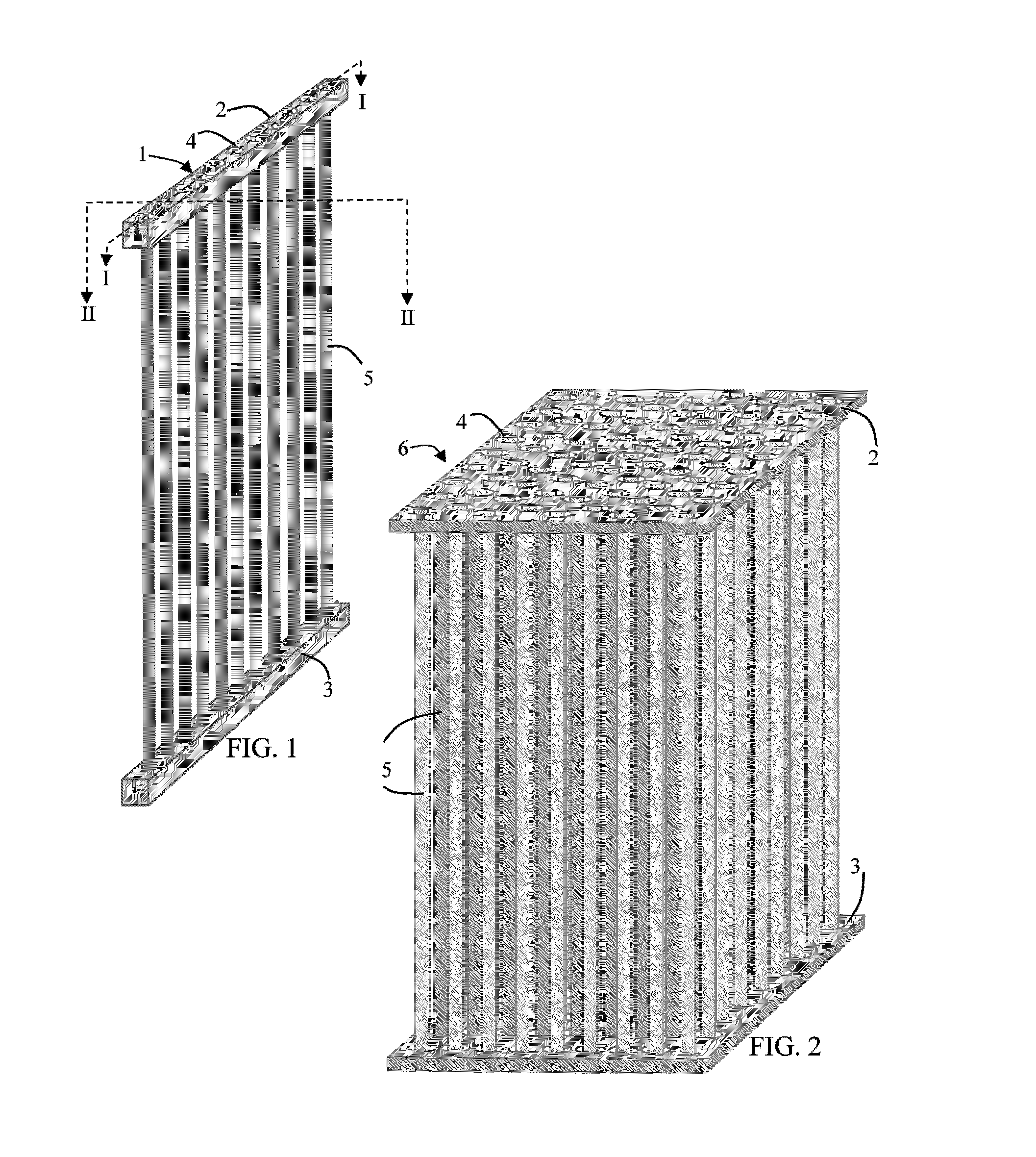
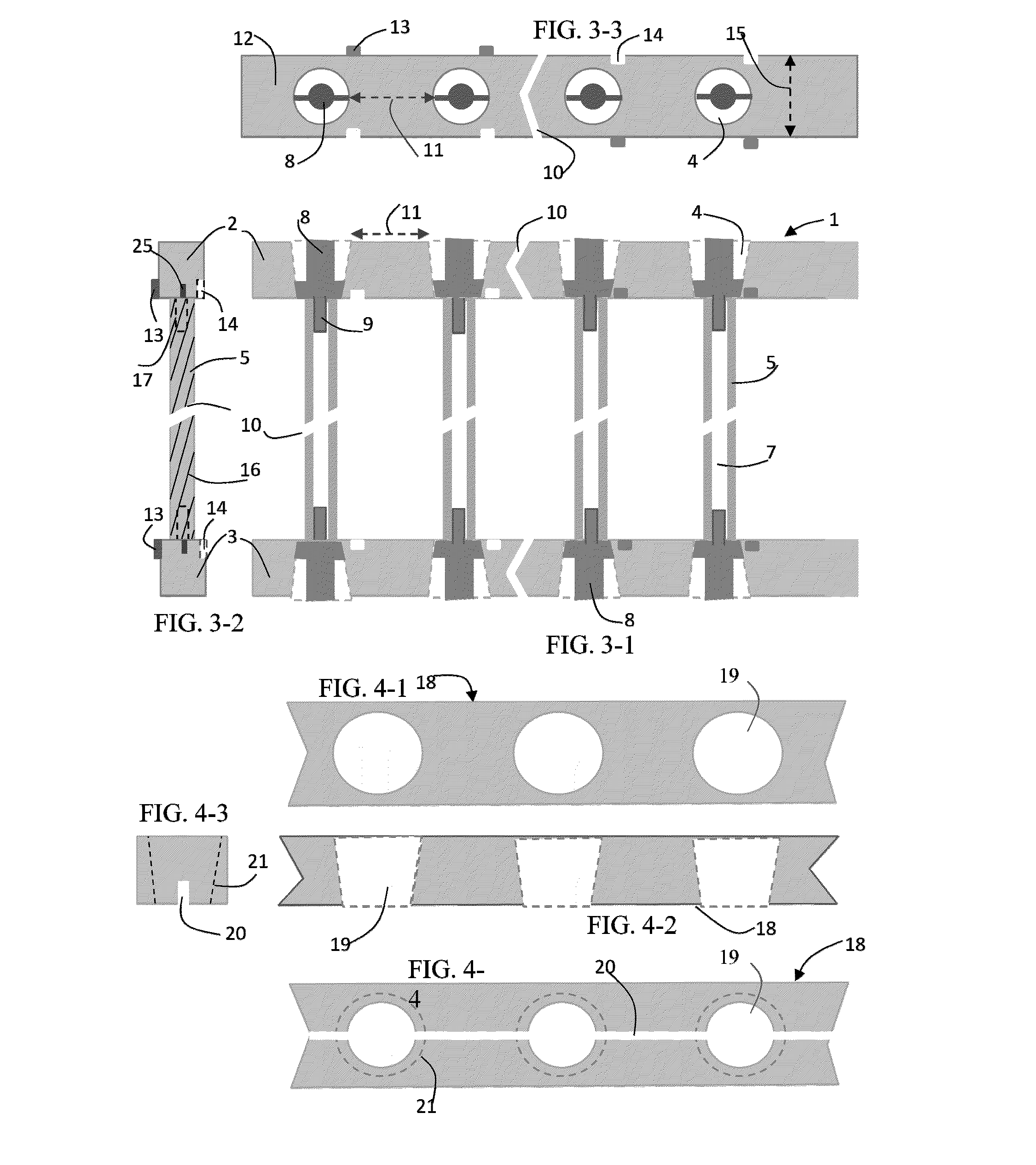
[0079]The plastic-rod-screen-fill (PRSF) invented by the present inventor has a disadvantage in employing large size rods (large diameter rod), since they require a large amount of materials for making solid rod. To complement such disadvantage of PRSF fabrication, the fabrication method of the plastic-tube-screen-fill (PTSF) using PVC tube is invented in the present invention. Any solid rod can be fabricated using a molten PVC injection machine like one step fabrication of PRSF, but plastic tube is made through molten plastic extruder. Hence, the fabrication of the PTSF can be accomplished by employing both injection and extrusion machines. Namely, the frame parts of PTSF are fabricated by the injection machine and the tubes fabricated by the extrusion machine, and then those parts are assembled to complete PTSF. The frame parts of PTSF include whole circular holes frame and tube holders. The whole circular holes frame is required, while PRSF has semi-circular holes frame, because ...


PUM

PropertyMeasurementUnit
slant angleaaaaaaaaaa
thicknessaaaaaaaaaa
thicknessaaaaaaaaaa

Abstract

The present invention involves a fabrication of plastic-tube-screen-fill using plastic tubes. The plastic-tube-screen-fill consists of several plastic tubes suspending between top and bottom tube holding perforated frames in the shape of a rectangular thin plate as a vertical string screen. The tube holding perforated frames are in same configuration to be used in two ways and fabricated by assembling a perforated frame and tube holding frame. The tube holding frame is a straight male band connector with several short solid rods positioned and fixed on band for push-fitting into the holes on perforated frame. The short solid rod on tube holding frame has a male push-fit connector on its lower part to be push-fitted into one edge of tube. The tubes used in the present invention are spiral corrugated tubes. Fabrication and assembling method of perforated frames, tube holding frames, and spiral corrugated tubes are described in the present invention.

Description

CROSS-REFERENCE TO RELATED APPLICATIONReferences Cited[0001]U.S. Patent Documents:[0002]U.S. application Ser. No. 13 / 053,382, Mar. 22, 2011. Park[0003]U.S. Application No. 61 / 726,928, Nov. 21, 2012. Park[0004]U.S. Application No. 61 / 736,646, Dec. 13, 2012. Park[0005]U.S. Application No. 61 / 820,102, May 6, 2013. Park[0006]U.S. application Ser. No. 13 / 895,368, May 16, 2013. Park[0007]U.S. application Ser. No. 13 / 888,327, Jun. 6, 2013. Park[0008]Foreign Patent Documents:KR100393126Jul. 18, 2003ParkKR100516391Sep. 14, 2005ParkKR100516392Sep. 14, 2005ParkPCTWO 2005 / 008159 A1Jan. 27, 2005Park[0009]Other Publications[0010]Dominick V. Rosato, et al, Injection Molding Handbook, 3rd Edition, Kluwer Academic Publishers, Norwell, Mass. 02061, USA.[0011]Robert A. Malloy, Plastic Part Design for Injection Molding An Introduction, Department of Plastic Engineering, University of Massachusetts, Lowell, Mass. 01854, USA.[0012]The plastic extrusion process for tube, hose, pipe, and rod, Http: / / dehwa....

Claims


Application Information

Patent Timeline
Patent Type & Authority Applications(United States)
IPC IPC(8): F28F1/08F16L3/22B01F3/04B29C49/00B29D16/00
CPCF28F1/08B29C49/0015B29D16/00B29L2023/18F16L3/22B29K2101/00B29L2016/00B01F3/04B29K2027/06B29C49/04F28F21/06F28F25/082F28D3/04F28F1/06
Inventor PARK, CHONG MOOK
Owner PARK CHONG MOOK
Why Eureka
Try Eureka