Transmission for vehicle and method for operation of a transmission

a transmission and vehicle technology, applied in mechanical equipment, transportation and packaging, gearing, etc., can solve the problem of relatively large structural complexity of the transmission, and achieve the effect of simple operation, low structural complexity, and simple structure of the transmission

Active Publication Date: 2015-05-07
ZF FRIEDRICHSHAFEN AG
View PDF3 Cites 48 Cited by
  • Summary
  • Abstract
  • Description
  • Claims
  • Application Information

AI Technical Summary

Benefits of technology

[0013]An objective of the present invention, therefore, is to provide a method for operating a transmission and a transmission that entail little structural complexity and with which as many powershiftable gears as possible can be obtained. In addition, an objective of the present invention is to provide a method for operating a transmission and a transmission, such that the structure of the transmission is simple and hence inexpensive and the transmission can be operated simply and thus inexpensively. Finally, an objective of the present invention is to indicate an alternative transmission and an alternative method for operating a transmission.

Problems solved by technology

This has the disadvantage that the structural complexity of the transmission is relatively great for the number of power-shiftable gears that can be obtained.

Method used


Image

  • Transmission for vehicle and method for operation of a transmission
  • Transmission for vehicle and method for operation of a transmission
  • Transmission for vehicle and method for operation of a transmission

Examples


first embodiment

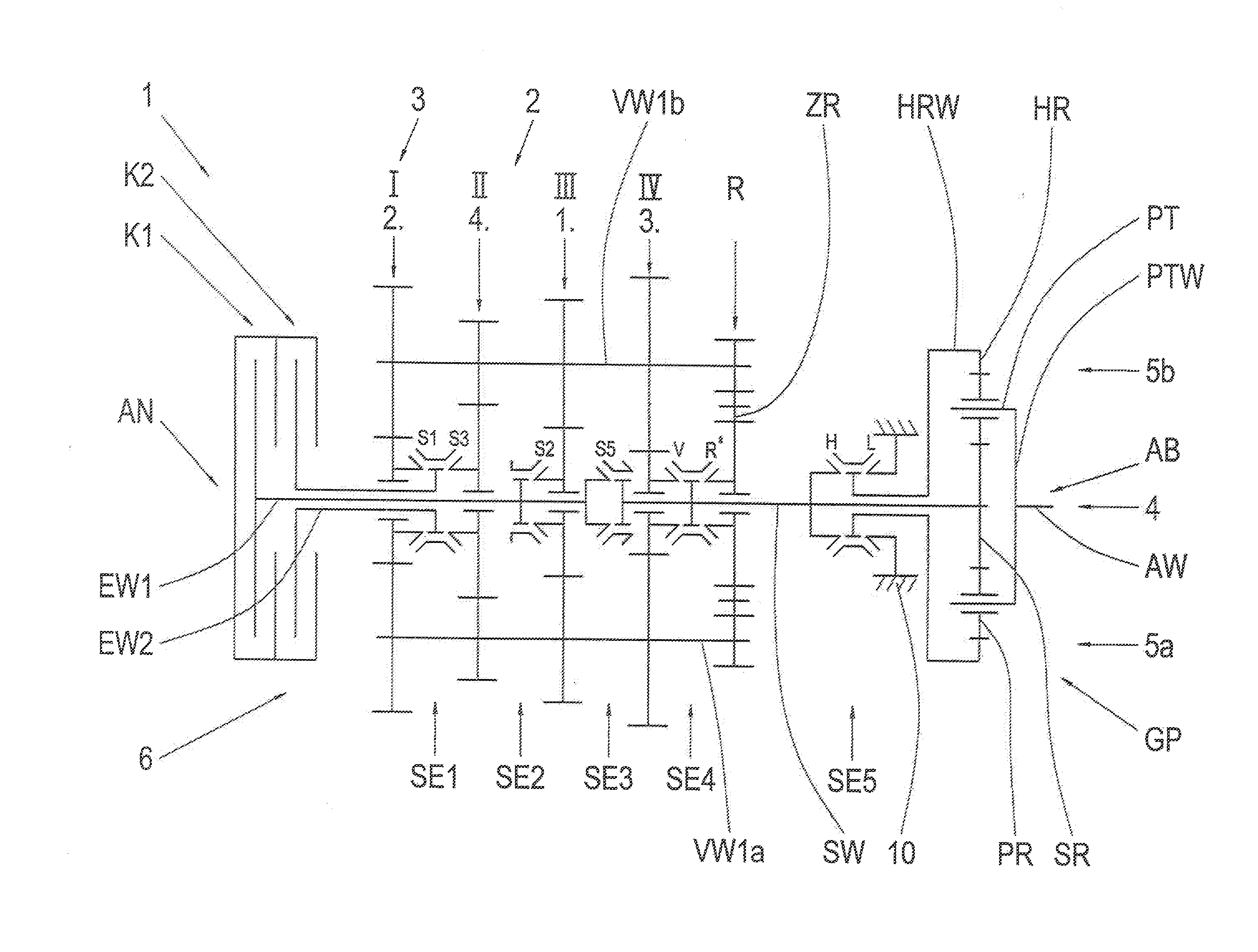
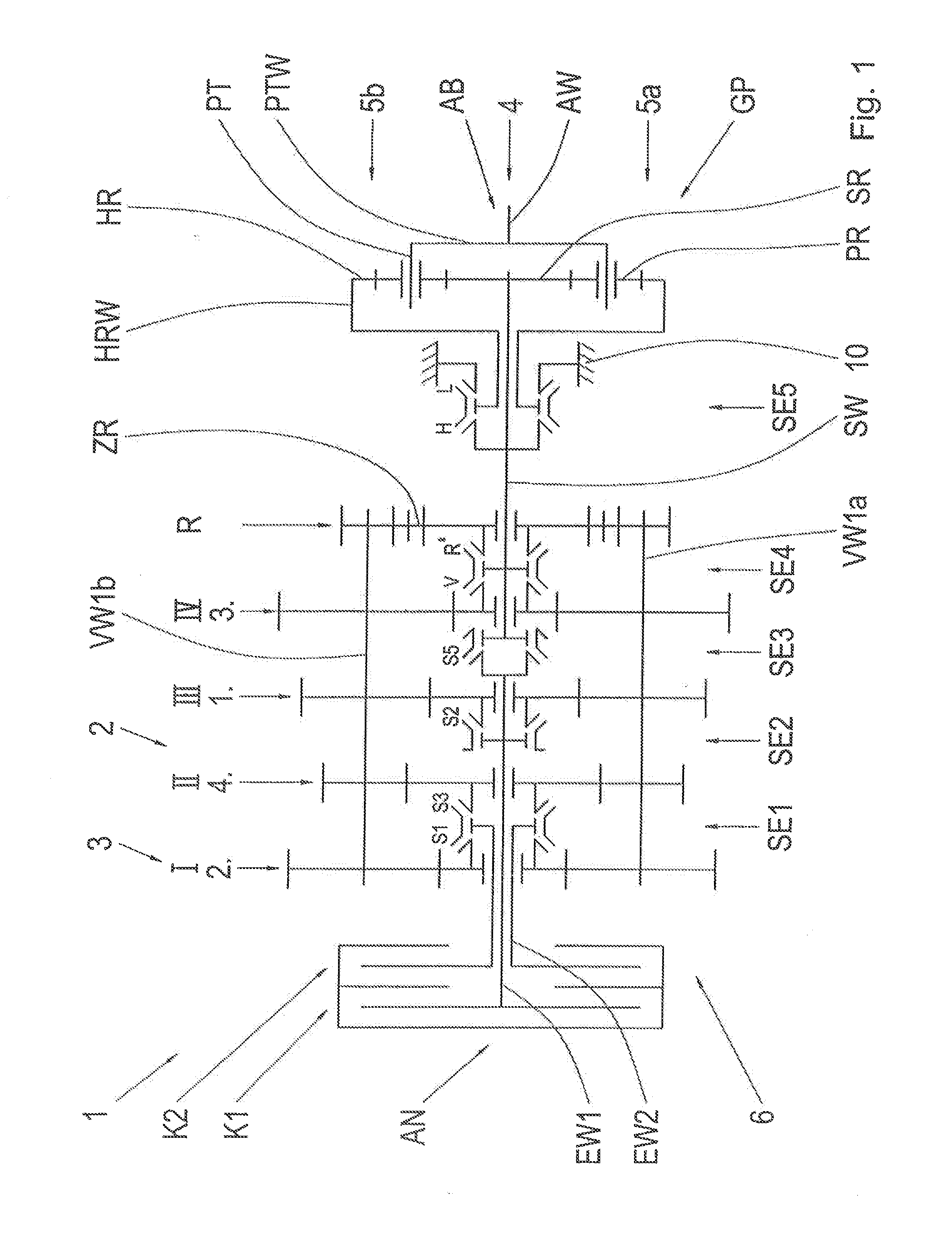
[0080]FIG. 1 shows a transmission according to the present invention.

[0081]In FIG. 1 the index 1 denotes a transmission in the form of a dual-clutch transmission. The dual-clutch transmission 1 has two powershift elements in the form of clutches K1 and K2. By means of the dual clutch K1, K2 the drive input side AN can be coupled or connected to the drive output side AB of the transmission 1 for the transmission of force and torques. For this purpose the first clutch K1 is connected to a first input shaft EW1 and the second clutch K2 is connected to a second input shaft EW2. The first input shaft EW1 is a solid shaft, whereas the second input shaft EW2 is a hollow shaft. The two input shafts EW1, EW2 are arranged coaxially with and parallel to one another on an input shaft axis 4.

[0082]In addition, the transmission 1 comprises two partial transmissions 2, 3. The first partial transmission 2 can be coupled to the first input shaft EW1 and the second partial transmission 3 can be coupl...

second embodiment

[0110]FIG. 7 shows a method for operating a transmission according to FIG. 5 in accordance with the present invention.

[0111]FIG. 7 essentially shows a shifting matrix as in FIG. 6 for operating a transmission as in FIG. 5. Otherwise than in the shifting matrix of FIG. 6, the shifting matrix of FIG. 7 comprises an additional coupling gear in the second partial transmission 3, which is added as a new fifth forward gear V5 directly before the direct gear V6 in the main transmission. In this case the forward gear V5 produces the transmission ratio of a single geometrical gear interval, in this case for example of 1.27. The new direct gear is therefore the sixth forward gear V6. The sequential powershifting during the shift from the fourth forward gearV4 to the fifth forward gear V5 is enabled by a supported gearshift: starting from the fourth forward gear V4, the direct gear, i.e. the sixth forward gear V6, is preselected in the first partial transmission 2. With the clutch K1 slipping ...

third embodiment

[0117]FIG. 9 shows a method for operating the transmission according to FIG. 8a in accordance with the present invention.

[0118]In FIG. 9 a shifting matrix is now shown for a transmission according to FIG. 8a. In this case an additional coupling gear is added in the second partial transmission 3 as a new fifth forward gear V5, and this as the gear immediately before the direct gear, now the forward gear V6 in the main transmission. The coupling gear produces the transmission ratio of the single geometrical gear interval, with φ=1.30 in FIG. 9 in this case. The new direct gear is therefore the sixth forward gear V6. Sequential powershifting is obtained in the shift from the fourth forward gear V4 to V5 by a supported gearshift: starting from the fourth forward gear V4, the direct gear V6 is preselected in the first partial transmission 2. With the clutch K1 slipping the traction force is supported, while in the second partial transmission 3 a load-free gearshift from the fourth forwar...


PUM


Abstract

The invention concerns a method for operating a transmission, in particular a dual-clutch transmission for a motor vehicle, which comprises at least two partial transmissions each of the partial transmissions having at least one input shaft on a drive input side of the transmission, which are arranged on an input shaft axis, an output shaft as the drive output shaft of the at least two partial transmissions on a drive output side of the transmission, wherein the drive output shaft is arranged on the input shaft axis or on at least one countershaft axis, in particular one that is parallel to the input shaft axis, an intermediate gear system on the at least one countershaft axis with at least one countershaft, wherein at least one of the input shafts can be connected by way of at least one gear plane and/or at least one shifting element to the drive output shaft, wherein at least four gear planes are arranged for obtaining forward gears and at least six shifting elements are provided and wherein on the at least one countershaft axis in each case only one countershaft is arranged, which has only transmission elements in the sense of fixed wheels for the one countershaft concerned, wherein by means of the transmission at least a plurality of forward gears and/or reverse gears can be obtained, and wherein at least one of the gears obtainable by means of the transmission is designed as a direct gear, such that when the direct gear is engaged all the shifting elements for coupling the intermediate gear system via the gear planes into the force flow can be disengaged, wherein each gear plane can be coupled by means of a shifting element arranged on the input shaft axis to a shaft, and wherein the gear next-lower than the direct gear is designed as a coupling gear.
The invention also concerns a transmission and a motor vehicle having a transmission.

Description

[0001]This application claims priority from German patent application serial no. 10 2013 222 510.5 filed Nov. 6, 2013.FIELD OF THE INVENTION[0002]The invention concerns a method for operating a transmission, in particular a dual-clutch transmission for a motor vehicle, which comprises at least two partial transmissions each of which has at least one input shaft on a drive input side of the transmission, which input shafts are arranged on an input shaft axis, an output shaft as the drive output shaft of the at least two partial transmissions on a drive output side of the transmission, the drive output shaft being arranged on the input shaft axis or on at least one countershaft axis, in particular one that is parallel to the input shaft axis, an intermediate gear system on the at least one countershaft axis, having at least one countershaft, wherein at least one of the input shafts can be connected by way of at least one wheel plane and / or at least one shifting element to the drive ou...

Claims


Application Information

Patent Timeline
Patent Type & Authority Applications(United States)
IPC IPC(8): F16H37/04
CPCF16H37/042F16H2200/0095F16H2200/0073F16H37/046F16H3/093F16H37/04F16H2200/00F16H61/688F16H3/006F16H2200/0091F16H2200/0078F16H61/702Y10T74/19233
Inventor MITTELBERGER, CHRISTIANBLATTNER, STEFANHUNOLD, BERNARDLUBKE, ECKHARDTKALTENBACH, JOHANNES
Owner ZF FRIEDRICHSHAFEN AG
Why Eureka
Try Eureka