
Breach detection in solid structures

a solid structure and detection technology, applied in the field of medical devices and methods, can solve the problems of stress and fatigue of manipulation, breaching of solid structures, and wear and tear at the site of manipulation stress and fatigue, so as to enhance sensitivity and reliability, minimize potential disruption of structure integrity, and expand the coverage area of detection

Active Publication Date: 2015-05-07
SENSURTEC
View PDF2 Cites 0 Cited by
  • Summary
  • Abstract
  • Description
  • Claims
  • Application Information

AI Technical Summary

Benefits of technology

Enables early detection of device failure, allowing for timely replacement and reducing the risk of complications, while maintaining the device's performance and structural integrity, and can be monitored by patients in a cost-effective and non-invasive manner.

Problems solved by technology

Typically the solid structures are subject to breach in areas where there is extensive contact between the device and body tissues or with an external object or between different parts of the device.
If the device is manipulated periodically, the area of wear and tear is at the site of stress and fatigue of the manipulation.
In particular, the breach will typically close an open region within the signaling circuit to cause, enable, disable, or alter the signal emission.

Method used


Image

  • Breach detection in solid structures
  • Breach detection in solid structures
  • Breach detection in solid structures

Examples


Embodiment Construction

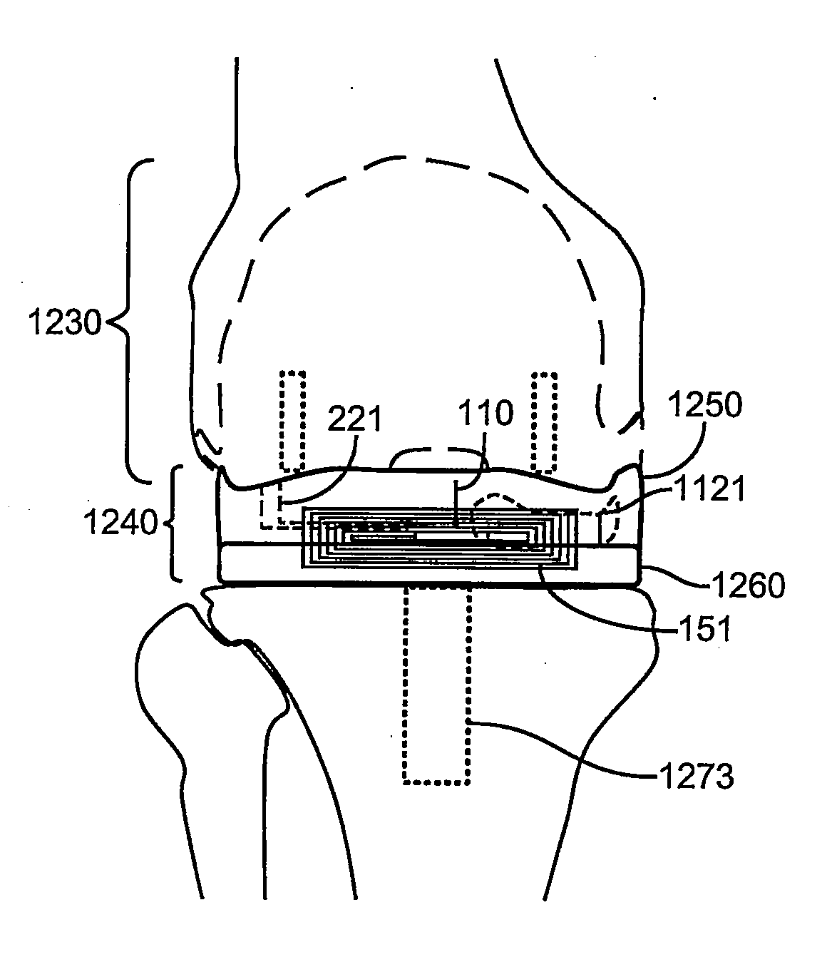
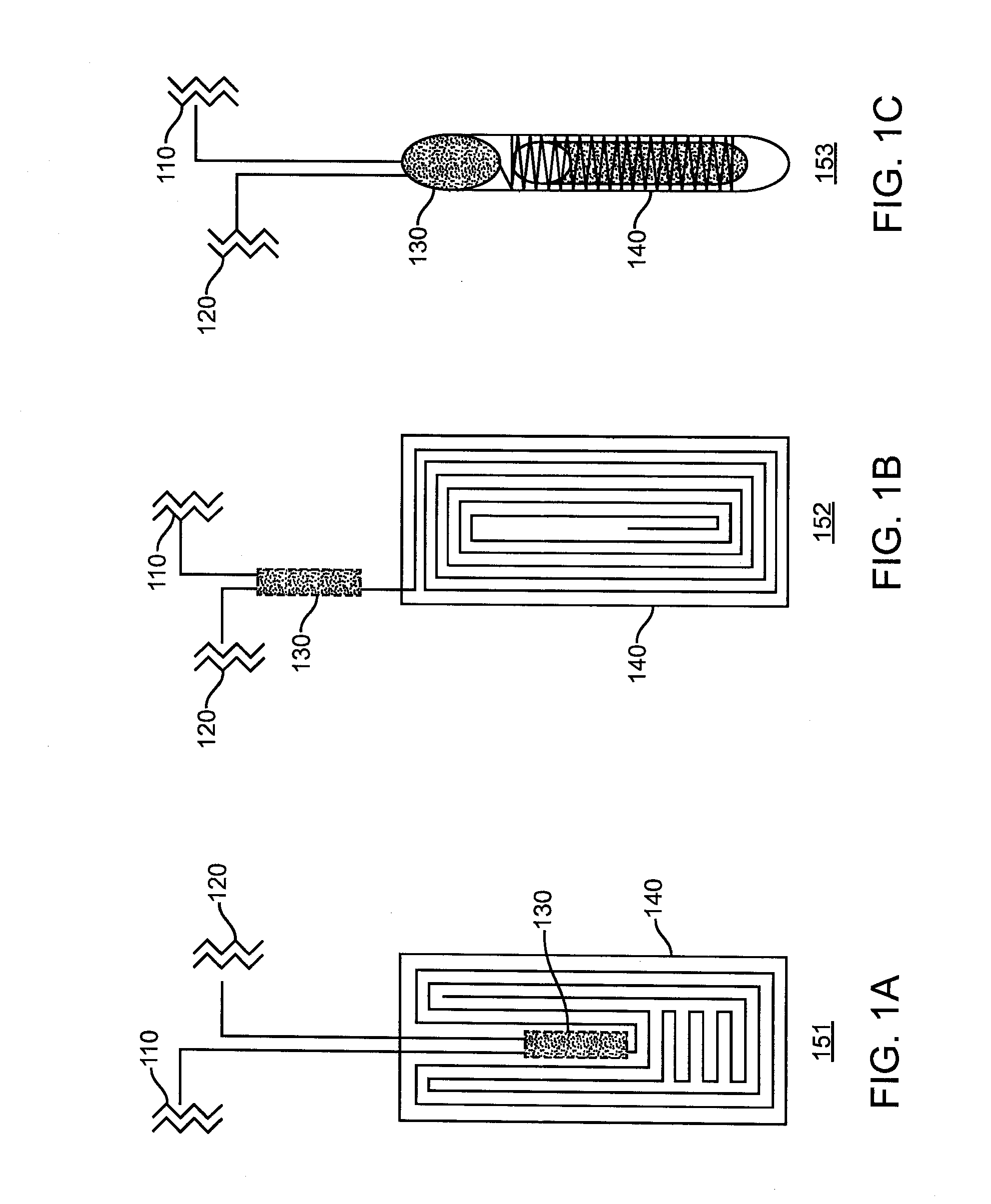
[0053]Referring now to FIGS. 1A-1C, the radiofrequency circuitry of the device is shown in three configurations, each with four major parts, a first conductor 110, a second conductor 120 (a distal end for detection shown in figures below in more detail), a logic circuit 130, and an antenna 140. The logic circuit 130, unless split into distinct parts, for the descriptive purposes here includes the transmitter and transponder. Conductors 110 and 120 are electrically isolated from each other until a breach exposing the conductor 120 to an electrically conductive fluid intruding into said breach bridges them. In circuitry 151, the logic circuit 130 is on the same substrate as the antenna 140. In circuitry 152, the logic circuit 130 is fixed on another substrate apart from the antenna 140 to accommodate design requirements for size and location, esp. to enhance sensitivity, specificity, or robustness. In circuitry 153, the logic circuitry 130 and a ferrite core antenna 140 is fixed insid...


PUM


Abstract

An implantable device includes at least one solid structure having an external surface and a volume beneath the surface. One or more of a first conductor or set of conductors is disposed externally and / or internally on or within the structure and an array of elongate electrically conductive elements are disposed radially outwardly within the volume. A breach is detected when a conductive fluid intrudes into the volume through the surface.

Description

CROSS-REFERENCE TO RELATED APPLICATIONS[0001]This application is a continuation of U.S. patent application Ser. No. 13 / 349,327 (Attorney Docket No. 41680-704.201), filed Jan. 12, 2012, which claims the benefit of U.S. Provisional Application No. 61 / 432,461 (Attorney Docket No. 41680-704.101), filed Jan. 13, 2011, the full disclosures of which are incorporated herein by reference.BACKGROUND OF THE INVENTION[0002]1. Field of the Invention[0003]The present invention relates generally to medical apparatus and methods. More particularly, the present invention relates to implantable devices and methods and systems for detecting their dysfunction or impending dysfunction.[0004]Implantable medical devices, particularly those indicated for long term use in the human body, are highly regulated and must meet certain safety requirements. It is known that when a device is implanted in the body, the materials forming the cover and structural elements of the device may degrade and fatigue over tim...

Claims


Application Information

Patent Timeline
Patent Type & Authority Applications(United States)
IPC IPC(8): A61F2/30A61N1/37A61M5/50A61N1/36A61M5/142A61F2/24A61N1/39
CPCA61F2/30721A61F2/30A61F2/24A61N1/3706A61N1/3925A61N1/36142A61F2002/30677A61M5/5086A61M2205/0233A61M2205/3523A61F2002/30052A61F2002/30581A61M5/14276A61B5/076A61B5/686A61B2560/0276A61F2/32A61F2002/3067A61N1/37A61N1/37258A61F2/488A61B5/4851A61B5/74A61M2205/15
Inventor CHEN, RICHARD D.Y.
Owner SENSURTEC
Learn More