
Integrated container-type torque sensor motor

a torque sensor and integrated container technology, applied in the direction of rider propulsion, vehicle components, dynamo-electric machines, etc., can solve the problems of low reliability of sensor signals and limited use, and achieve enhanced sensitivity and reliability of magnetic induction, improved magnetic induction effect, and improved reliability

Inactive Publication Date: 2014-09-11
WUXI SHANGGE IND DESIGN
View PDF3 Cites 9 Cited by
  • Summary
  • Abstract
  • Description
  • Claims
  • Application Information

AI Technical Summary

Benefits of technology

The patent text describes a floating ratchet sensor ring assembly for a motor that includes a magnetic steel piece that corresponds in position to the magnetic induction of a Hall element. This improves the sensitivity and reliability of magnetic induction, preventing signal distortion. The motor casing has a high degree of standardization and is widely usable. The invention has significant magnetic induction effects and is easy to produce, install, and maintain.

Problems solved by technology

This lowers the reliability of the sensor signal and the production processes are more to increase the production cost, so that its use is limited.

Method used


Image

  • Integrated container-type torque sensor motor
  • Integrated container-type torque sensor motor
  • Integrated container-type torque sensor motor

Examples


Embodiment Construction

[0022]Embodiments of the present invention will now be described, by way of example only, with reference to the accompanying drawings.

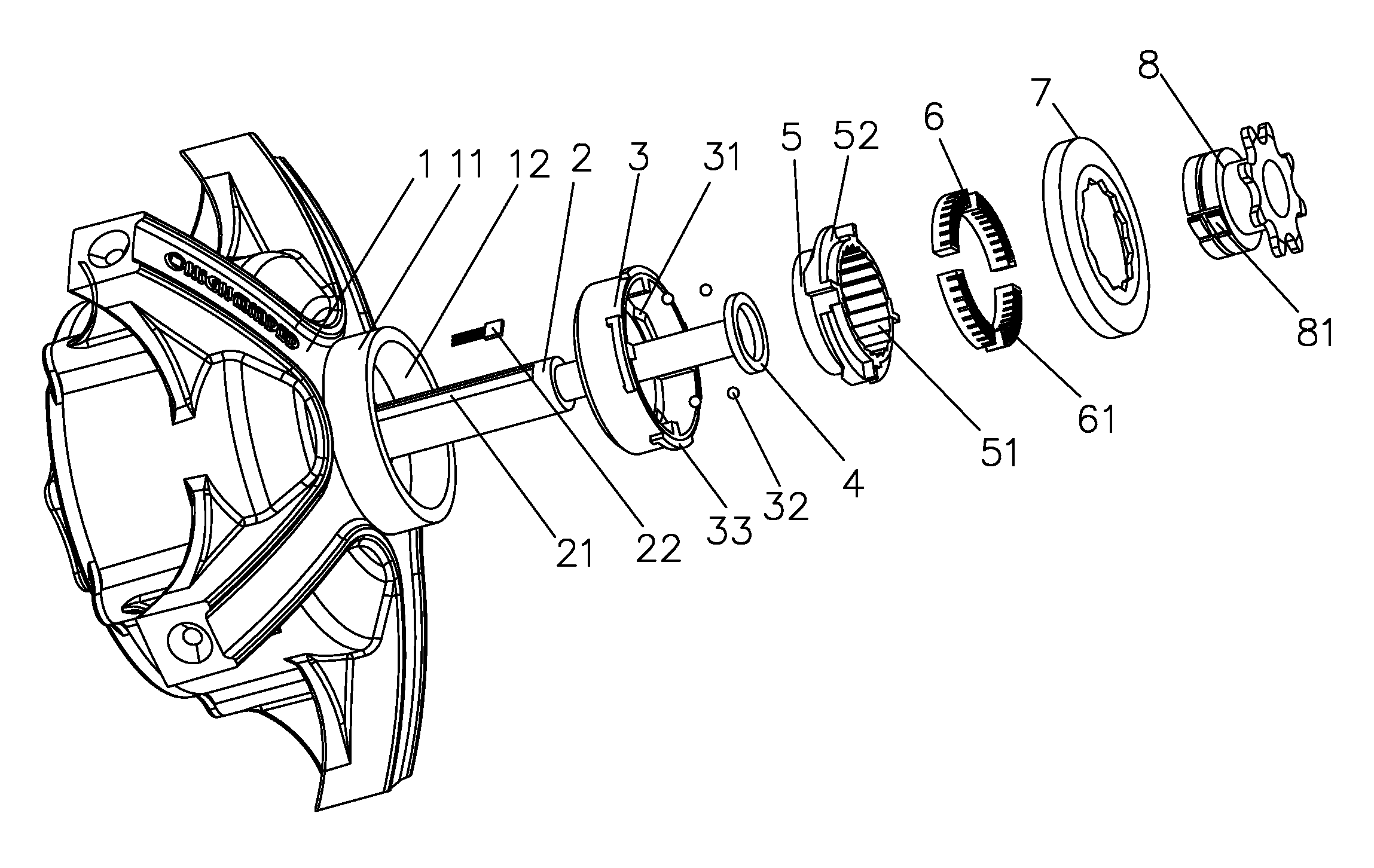
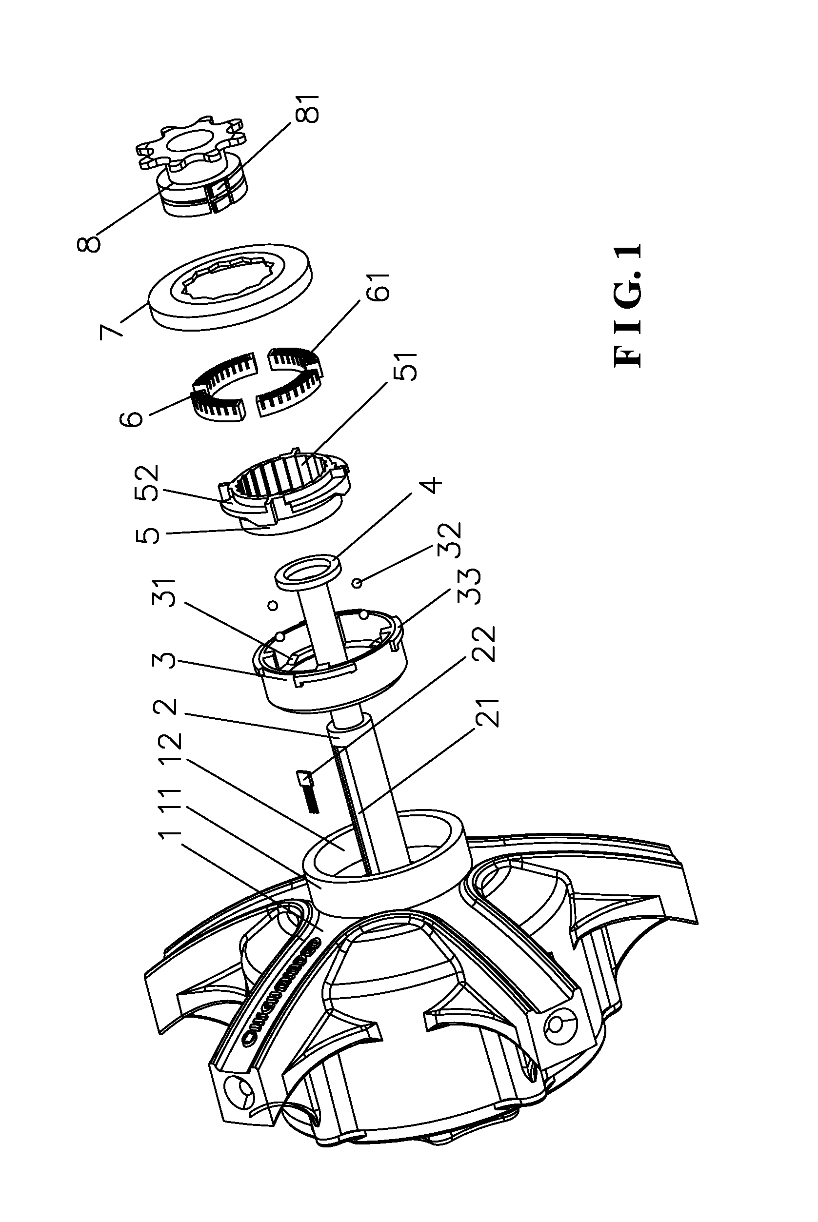
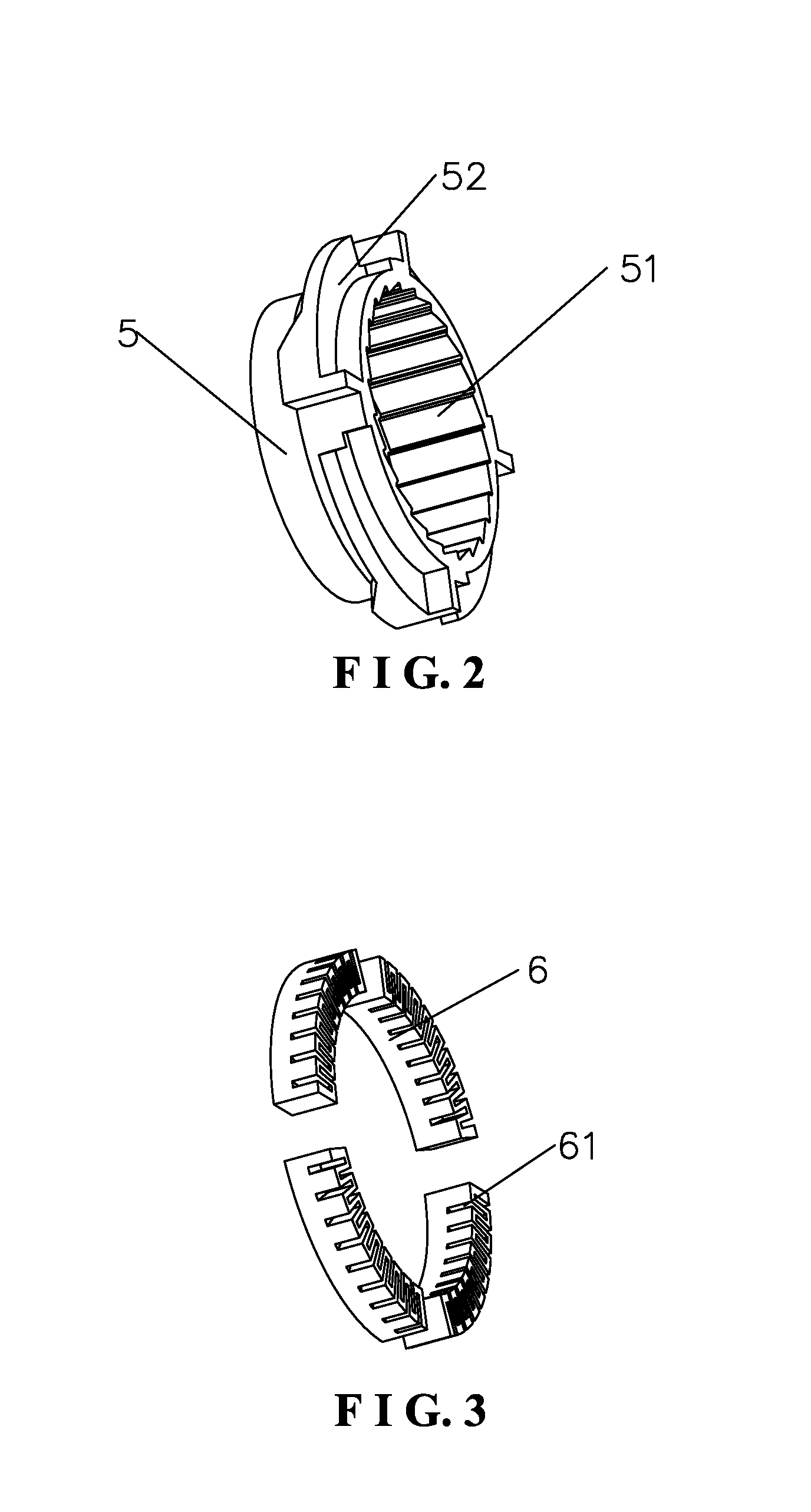
[0023]As shown in FIG. 1 to FIG. 3, the present invention discloses an integrated container-type torque sensor motor. The integrated container-type torque sensor motor according to a preferred embodiment of the present invention comprises a motor shaft 2 and a motor casing 1 disposed on the motor shaft 2. The motor shaft 2 is provided with a flywheel 8 for driving. The motor casing 1 has a ring-shaped protrusion 11 around the motor shaft 2 to form a hollow cavity 12. The hollow cavity 12 is adapted to accommodate and install a fixed guiding slip ring 3. A floating ratchet sensor ring assembly comprises of a ratchet sensor ring 5, an elastic return member 6 cooperating with the ratchet sensor ring 5, and an end cap 7 rotatably connected with the fixed guiding slip ring 3. After the elastic return member 6 is positioned on the ratchet sensor is ring 5, ...


PUM


Abstract

An integrated container-type torque sensor motor is provided. Disposed on a motor housing along the direction of a motor shaft is a hollow cavity formed by a ring-shaped protrusion; contained in the hollow cavity is a fixed guiding slip ring; the fixed guiding slip ring dynamically matches with a floating sensor ring assembly having ratchet teeth and a magnetic steel piece; the ratchet teeth of a flywheel mating with the cogging distributed in a ring shape in a sensor ring having ratchet teeth; disposed on the motor shaft is a Hall element, the magnetic steel piece cooperating with the Hall element by means of magnetic induction, thereby outputting an electric signal to control a vehicle to enhance the force for rotation. For this motor, all Hall elements are disposed on the motor housing, thereby solving the conflict between function configuration and space occupation, and enabling significant magnetic induction effects.

Description

BACKGROUND OF THE INVENTION[0001]1. Field of the Invention[0002]The present invention relates to a vehicle electric power transmission, and more particularly to an electric power sensor motor for a vehicle to enhance the force.[0003]2. Description of the Prior Art[0004]In the field of bike electric power sensors, Chinese Patent Application No. 201110125438.9 discloses “ELECTRIC POWER SENSOR STRUCTURE COOPERATING WITH REAR FORK OF BIKE”. The bottom of one side of the rear fork of the bike has a trough. A circuit board installed with Hall elements is fixed in the recess. The recess is further provided with a sensor which passes through a slot of the bottom of the recess and is disposed on a movable rear shaft. A permanent magnet is provided on the sensor to cooperate with the Hall elements on the circuit board. The rear shaft is confined to move within the slot of the bottom of the recess. By using is movement of the rear shaft, the permanent magnet which is fixed relative to the rear...

Claims


Application Information

Patent Timeline
Patent Type & Authority Applications(United States)
IPC IPC(8): H02K11/00
CPCH02K11/0042B62M6/50B62M6/65H02K11/24
Inventor WANG, HUAN
Owner WUXI SHANGGE IND DESIGN
Learn More