
Methods, devices, and systems for obesity treatment

a technology of obesity treatment and devices, applied in the field of medical devices and methods, can solve the problems of change in the functioning of the circuit, change in resistance, capacitance or impedance across the conductor, breakage, disruption, etc., and achieve the effect of preventing the loss of inflating liquid medium, reducing the risk of abrasion or other trauma to the stomach lining, and being easily accessibl

Active Publication Date: 2016-10-04
FULFILLIUM
View PDF139 Cites 5 Cited by
  • Summary
  • Abstract
  • Description
  • Claims
  • Application Information

AI Technical Summary

Benefits of technology

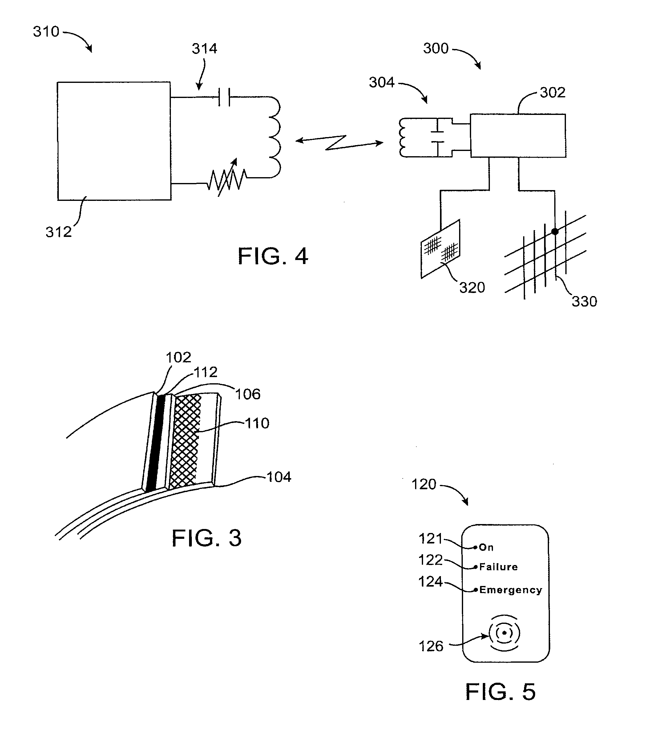
[0016]Alternatively, the circuit components may include spaced-apart conductors which are electrically coupled to the signaling circuit to “close” the signaling circuit to permit current flow when exposed to a body fluid and / or device contents by a wall breach. Alternatively, the circuit may be altered, enabled or otherwise modified by a sufficient flow of electrolytes to enable, interpret, disrupt, or modify a signal emission. The circuit components may include spaced apart conductors which are coupled to the signaling circuit to detect a change in resistance, capacitance, impedance, or voltage. Since the breach could be small and intermittent as it starts, it can be difficult to detect as a flow but the cumulative gain or loss of the electrolytes from the contents or surrounding body fluids could cause a change in the resistance, capacitance, or impedance across the conductors. Alternatively, the detection circuit is closed and the contact of the contents or the body fluids with the conductors could cause a break, disruption, or change in the functioning of the circuit. In the exemplary embodiments described below, the conductors may comprise meshes, films, or other relatively large surface areas covering most or all of the wall so that breach at any point in the wall will provide the intended electrically conductive bridging between the conductors. The coupling of the conductors may also cause, alter, or enable a signal emission to alert the patient of the breach or potential breach. The spaced-apart conductors can have anyone of a variety of shapes or configurations, continuous configurations, such as plates and films, or discontinuous configurations, such as lattices, meshes, and the like, can be placed in various locations, preferably near interior portions of the device where body fluids will pool to enhance sensitivity and reliability of the detection.
[0057]In addition to adjusting the size and / or buoyancy of the gastric balloon, it may become desirable or necessary to remove the balloon completely. To effect such removal, the balloon may be accessed transesophageally, typically using a gastroscope. The balloon may first be grasped or secured using a grasping tool. Then, one or more surfaces of the balloon may be penetrated or breached in order to release the contents of the balloon into the stomach. The contents may be biocompatible gasses or liquids so that release into the stomach will not be a concern. After the contents of the compartments have been released, the balloon may then be pulled through the patient's esophagus, for example by pulling with the grasping tool. It may be possible to pull the deflated gastric balloon through the working channel of the gastroscope, but more often the balloon will simply be withdrawn through the esophagus as the gastroscope is withdrawn. Optionally, a sheath or other protective cover may be placed over the deflated balloon in order to reduce the risk of trauma or injury to the esophagus upon withdrawal.

Problems solved by technology

These and other devices may contain potentially bioincompatible materials, such as batteries, circuitry, synthetic chemicals, and the like.
Since the breach could be small and intermittent as it starts, it can be difficult to detect as a flow but the cumulative gain or loss of the electrolytes from the contents or surrounding body fluids could cause a change in the resistance, capacitance, or impedance across the conductors.
Alternatively, the detection circuit is closed and the contact of the contents or the body fluids with the conductors could cause a break, disruption, or change in the functioning of the circuit.

Method used


Image

  • Methods, devices, and systems for obesity treatment
  • Methods, devices, and systems for obesity treatment
  • Methods, devices, and systems for obesity treatment

Examples


Embodiment Construction

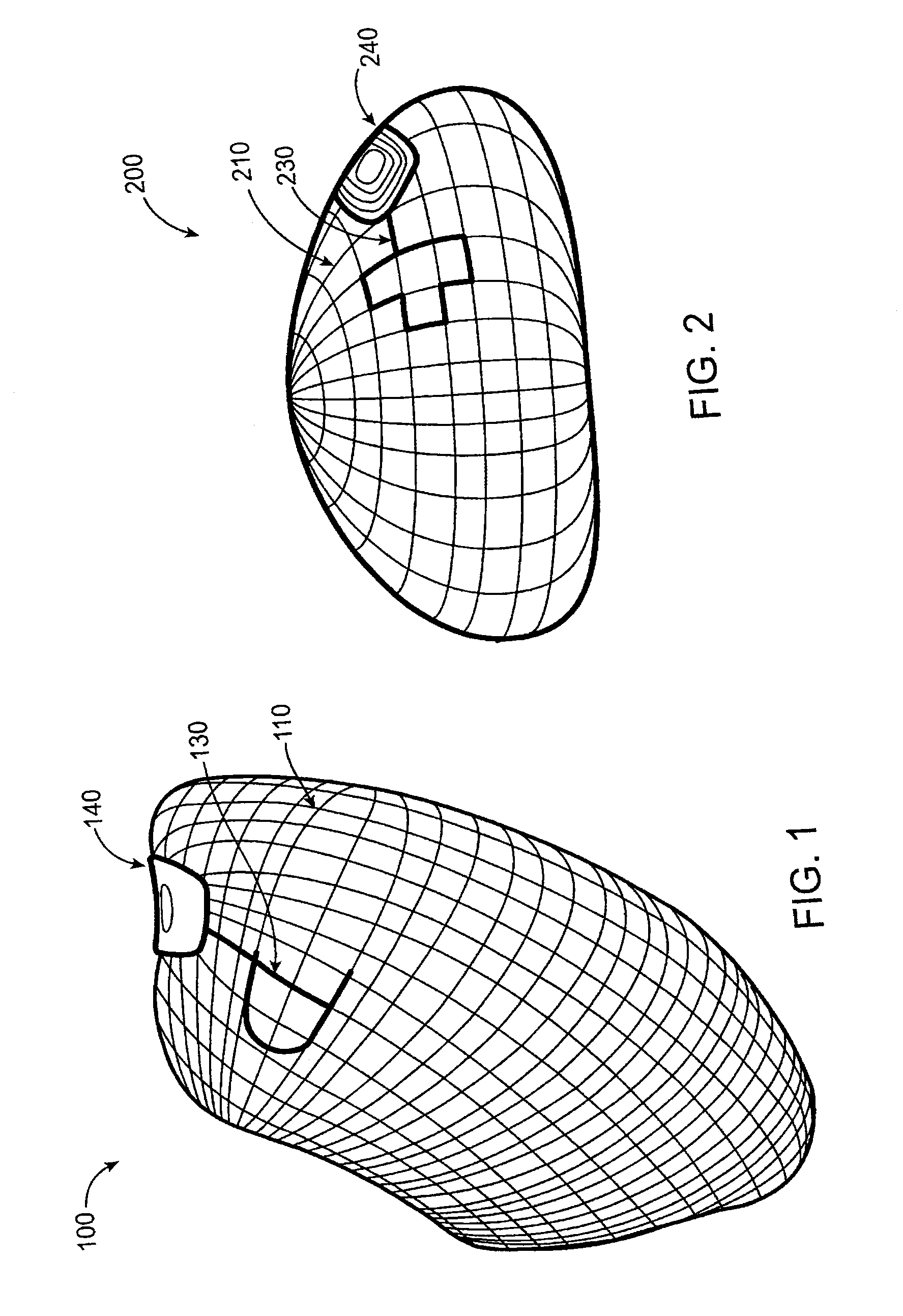
[0081]Referring now to FIG. 1, the gastric balloon 100 includes two electric probes. Probe 130 is on the external surface in contact with the surrounding tissues, body fluids, and contents of the stomach. Probes 130 and 110 can have any of a variety of shapes or configurations, including circular plates, lattices, films, and the like, cover all or a portion of the balloon or other device. Probe 110, shown here in a lattice configuration, provides the second probe incorporated in the wall of the balloon. The probe material could be any metal, polymer, fiber, or combination thereof, with or without any coating that can generate an electrical charge or enable flow of electric current when in contact with the stomach contents. The probes are connected electronically to the wireless transmitter 140, but are separated from each other by at least one layer of non-conductive material in the balloon wall. The transmitter can be a simple wireless signal generator triggered by an electric curr...


PUM


Abstract

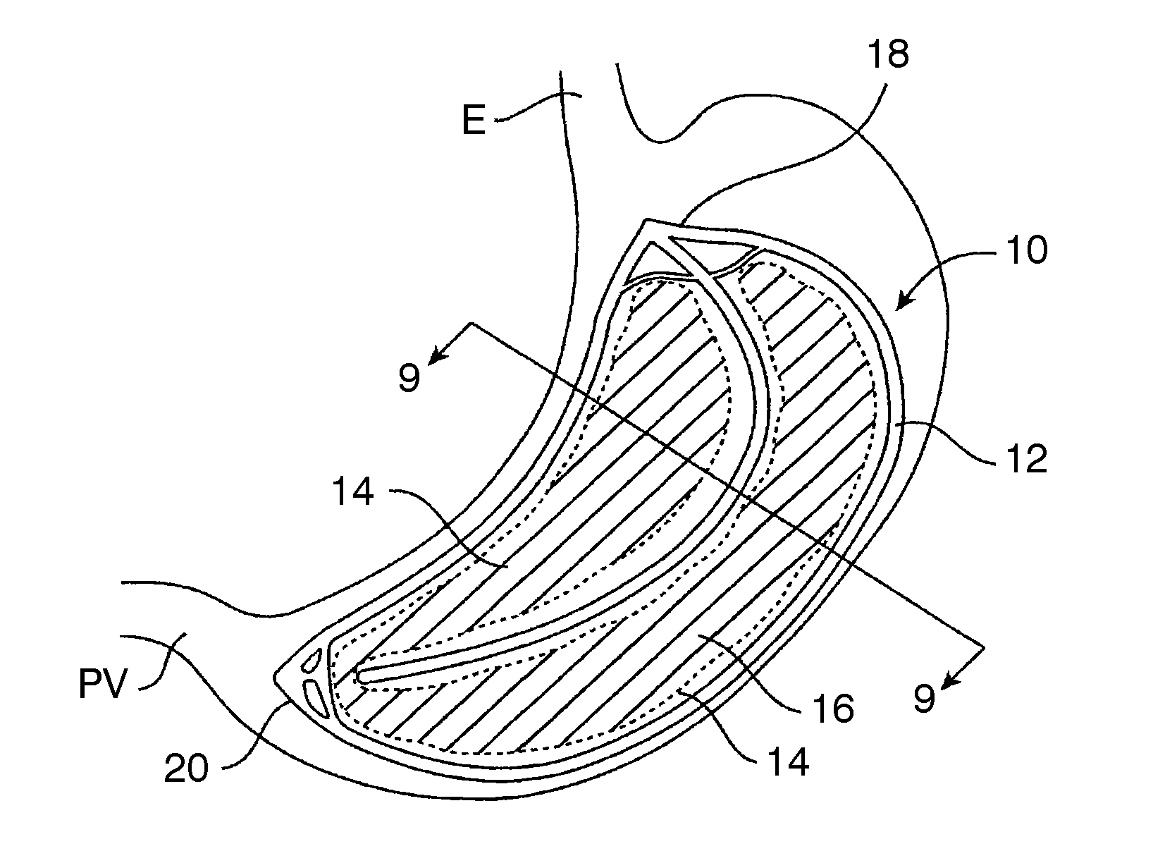
Upon filling multiple inflatable chambers of a gastric balloon structure in a patient's stomach, the gastric balloon structure assumes a natural three-dimensional kidney shape of the gastric cavity. A flexible central spine may span a gap between two inflatable chambers and may include lumens for inflation of one or both chambers. The plurality of compartments, when in an inflated state, may form a cavity therebetween through which food may pass and may leave in a stomach a residual volume of 10 ml to 100 ml.

Description

CROSS-REFERENCES TO RELATED APPLICATIONS[0001]This application is a continuation of and claims the benefit of priority from U.S. patent application Ser. No. 11 / 282,224, filed Nov. 18, 2005, which is a continuation-in-part of application Ser. No. 11 / 170,274, filed on Jun. 28, 2005 and issued Dec. 6, 2011 as U.S. Pat. No. 8,070,807 entitled “Wireless Breach Detection”, which was a continuation in-part of application Ser. No. 11 / 122,315, filed on May 3, 2005 and issued Nov. 29, 2011 as U.S. Pat. No. 8,066,780 entitled “Methods for Gastric Volume Control”, and claims the benefit under 35 USC §119(e) of prior provisional application No. 60 / 629,800, filed on Nov. 19, 2004, the full disclosures of which are incorporated herein by reference.BACKGROUND OF THE INVENTION[0002]1. Field of the Invention[0003]The present invention relates generally to medical apparatus and methods. More particularly, the present invention relates to implantable devices and methods and systems for detecting their ...

Claims


Application Information

Patent Timeline
Patent Type & Authority Patents(United States)
IPC IPC(8): A61F2/04A61F2/12A61B5/07A61N1/08G08B21/18A61F5/00A61B5/00
CPCA61F5/003A61B5/076A61B5/686A61B5/7282A61B5/746A61F2/12A61F5/0036A61F5/0046A61N1/08G08B21/18A61F2210/0061A61F2250/0002A61F2250/0003A61F2250/008A61N1/372A61B5/0028A61B2560/0276A61F5/0033
Inventor CHEN, RICHARD D. Y.JOHANSON, CRAIG AJONES, CHRISTOPHER SDAUSKARDT, REINHOLD HTAUB, MARC B
Owner FULFILLIUM
Learn More