
Extension tool

a technology of extension tool and extension rod, which is applied in the field of extension tools, can solve the problems of time-consuming and potentially dangerous procedures, and none of the prior art patents have solved the needs of the art, and achieve the effect of facilitating slidable displacement and preventing slidable displacement of the second pol

Inactive Publication Date: 2015-05-14
LOFLEY SR ROBERT G +1
View PDF8 Cites 1 Cited by
  • Summary
  • Abstract
  • Description
  • Claims
  • Application Information

AI Technical Summary

Benefits of technology

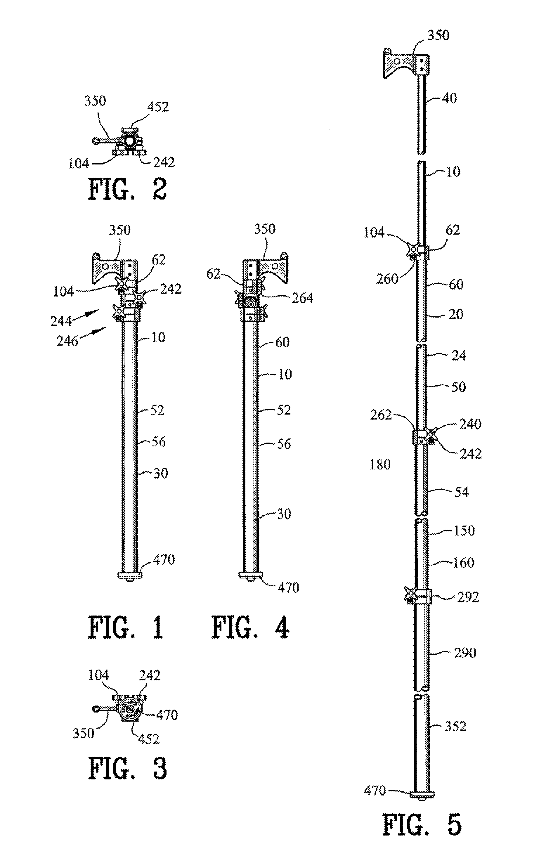
[0022]The present invention is defined by the appended claims with specific embodiments being shown in the attached drawings. For the purpose of summarizing the invention, the invention an relates to an improved extension tool. The extension tool comprises a first pole defining an interior bore and a first exterior surface with the first pole extending between a first end and a second end. A second pole defines a second exterior surface with the second pole extending between a first cod and a second end. The second pole is partially disposed in the first pole for defining a variable overall tool length. A slide controller includes a lower clamp and an upper clamp. The lower clamp has a primary arm and a secondary arm for defining a first coupler interior bore. The upper clamp has a primary arm and a secondary arm for defining a second coupler interior bore. The second end of the first pole is disposed in the first coupler interior bore of the lower clamp. A first clamp compressor extends between the primary arm and the secondary arm of the lower clamp and applying a compressive force between the primary arm and the secondary arm for defining a lower clamp lock and coupling the slide controller with the first pole. A second clamp compressor extends between the primary arm and the secondary arm of the upper clamp and applying a compressive force between the primary arm and the secondary arm for defining an upper clamp lock and preventing slidable displacement of the second pole relative to the first pole. The second clamp compressor applies a non-compressive force between the primary arm and the secondary arm for the upper clamp defining an upper slide guide. The upper slide guide facilitates the slidable displacement of the second pole relative to the first pole.
[0023]In a more specific embodiment of the invention, a bushing defines an internal bore and an exterior surface. The first end of the second pole is disposed and coupled to the internal bore of the bushing. The exterior surface of the bushing slidably engages with the interior bore of the first pole for defining a lower slide guide. The lower slide guide and the upper slide guide facilitate the slidable displacement of the second pole relative to the first pole.
[0024]In another embodiment of the invention, a third pole defines an interior bore and a third exterior surface with the third pole extending between a first end and a second end. The first pole is partially disposed in the third pole for defining a second variable overall tool length. A second slide controller includes a second lower clamp and an second upper clamp. The second lower clamp has a primary arm and a secondary arm for defining an third coupler interior bore. The second upper clamp has a primary arm and a secondary arm for defining an fourth coupler interior bore. The second end of the third pole is disposed in the third coupler interior bore of the second lower clamp. A third clamp compressor extends between the primary arm and the secondary arm of the second lower clamp and applies a compressive force between the primary arm and the secondary arm for defining a second lower clamp lock and coupling the second slide controller with the third pole. A fourth clamp compressor extends between the primary arm and the secondary arm of the second upper clamp and applies a compressive force between the primary arm and the secondary arm for defining an second upper clamp lock and preventing slidable displacement of the first pole relative to the third pole. The fourth clamp compressor applies a non-compressive force between the primary arm and the secondary arm for the second upper clamp defining a second upper slide guide. The second upper slide guide facilitating the slidable displacement of the first pole relative to the third pole.
[0027]In a more specific embodiment of the invention, a guard cover has a bottom shield plate coupled with a first side shield plate and a second side shield plate for defining a generally U-shaped shield channel. The guard cover includes an arcuate shape for positioning the bottom edge of the plate within the generally U-shaped shield channel. A couple maintains the guard cover to the plate. The guard cover protects the plate from damage due to engagement between the tool head and the object.

Problems solved by technology

This procedure is very time consuming and possibly dangerous activity since the railroad employee is required to climb the ladders on each of the railroad cars which are in many cases located between two adjacent railroad cars.
Although the aforementioned prior art have contributed to the development of the art of tools, none of these prior art patents have solved the needs of the art.

Method used


Image

  • Extension tool
  • Extension tool
  • Extension tool

Examples


Embodiment Construction

[0076]FIGS. 1-45 are various views of an extension tool 10. The extension tool 10 may be utilized for engaging a railroad car 300 as shown in FIGS. 25-33, however the extension tool 10 may be utilized as a support between two objects, for distancing an object from another object, or for applying a force upon an object that is distanced from another object.

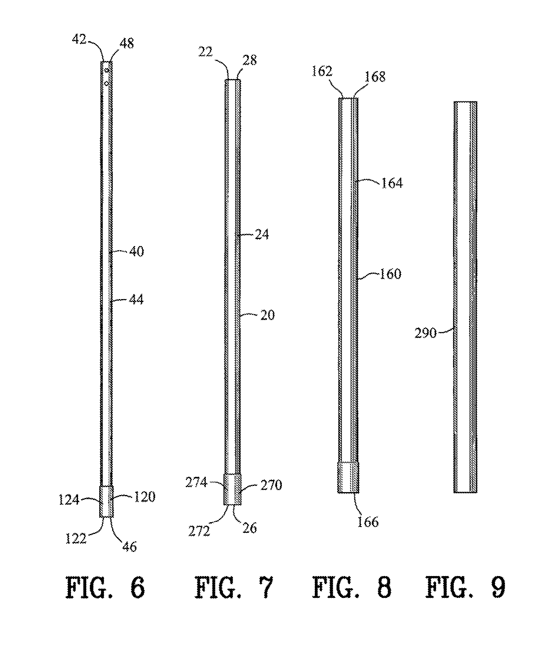
[0077]As best shown in FIGS. 1-24, the extension tool 10 comprises a first pole 20 defining a first interior bore 22 and a first exterior surface 24 with the first pole extending between a first end 26 and a second end 28. A second pole 40 defines a second interior bore 42 and a second exterior surface 44 with the second pole 40 extending between a first end 46 and a second end 48. The second pole 40 is partially disposed in the first pole 20 for defining a variable overall tool length 60. As the second pole 40 is withdrawn from the first pole 20, the variable overall tool length 60 increases as best shown in FIGS. 5, 7, 25, 29, 31...


PUM


Abstract

An extension tool is disclosed comprising a first pole and a second pole. The second pole is partially disposed in the first pole for defining a variable overall tool length. A slide controller includes a lower clamp and an upper clamp. The first pole is disposed in the lower clamp. A first clamp compressor applies a compressive force to the lower clamp for defining a lower clamp lock and coupes the slide controller with the first pole. A second clamp compressor applies a compressive force to the upper clamp for defining an upper clamp lock and prevents slidable displacement of the second pole relative to the first pole. The second clamp compressor applies a non-compressive force to the upper clamp for defining an upper slide guide. The upper slide guide facilitates the slidable displacement of the second pole relative to the first pole.

Description

CROSS-REFERENCE TO RELATED APPLICATIONS[0001]This application claims benefit of U.S. Patent Provisional application No. 61 / 459,635 filed Dec. 16, 2010. All subject matter set forth in provisional application No. 61 / 459,635 filed Dec. 16, 2010 is hereby incorporated by reference into the present application as if fully set forth herein.BACKGROUND OF THE INVENTION[0002]1. Field of the Invention[0003]This invention relates to tools and more particularly to the extension tool for displacing an object.[0004]2. Background of the Invention[0005]Various types of tools have been advised in the past for moving or rotating objects. One particular application of these tools is the rotation of a break actuator for a wheel brake located on a railroad car. Typically, the railroad car wheel break is actuated by rotating the break actuator. The break actuator may include a wheel having a plurality of spokes extending from a central hub. The rotation of the wheel rotates the hub and a shaft attached ...

Claims


Application Information

Patent Timeline
Patent Type & Authority Applications(United States)
IPC IPC(8): B25G1/04B61H13/02
CPCB61H13/02B25G1/04F16B7/1418F16B7/1472Y10T403/32491
Inventor LOFLEY, SR., ROBERT G.LOFLEY, JR., ROBERT G.
Owner LOFLEY SR ROBERT G
Learn More