Video display terminal, video transmission terminal, video communication system, video display method, video transmission method, and computer-readable recording medium recording program

a video display terminal and video transmission technology, applied in the field of video display terminals, video transmission terminals, video display methods, video transmission methods, etc., can solve the problems of unicast transmission, increase in data delay amount, and decrease in communicable data amoun

Inactive Publication Date: 2015-05-14
OLYMPUS CORP
View PDF7 Cites 40 Cited by
  • Summary
  • Abstract
  • Description
  • Claims
  • Application Information

AI Technical Summary

Problems solved by technology

Thereby, a decrease in a communicable data amount and an increase in a data delay amount occur.
However, when high quality and high reliability of the video are required, unicast transmission is necessary.

Method used


Image

  • Video display terminal, video transmission terminal, video communication system, video display method, video transmission method, and computer-readable recording medium recording program
  • Video display terminal, video transmission terminal, video communication system, video display method, video transmission method, and computer-readable recording medium recording program
  • Video display terminal, video transmission terminal, video communication system, video display method, video transmission method, and computer-readable recording medium recording program

Examples


first embodiment

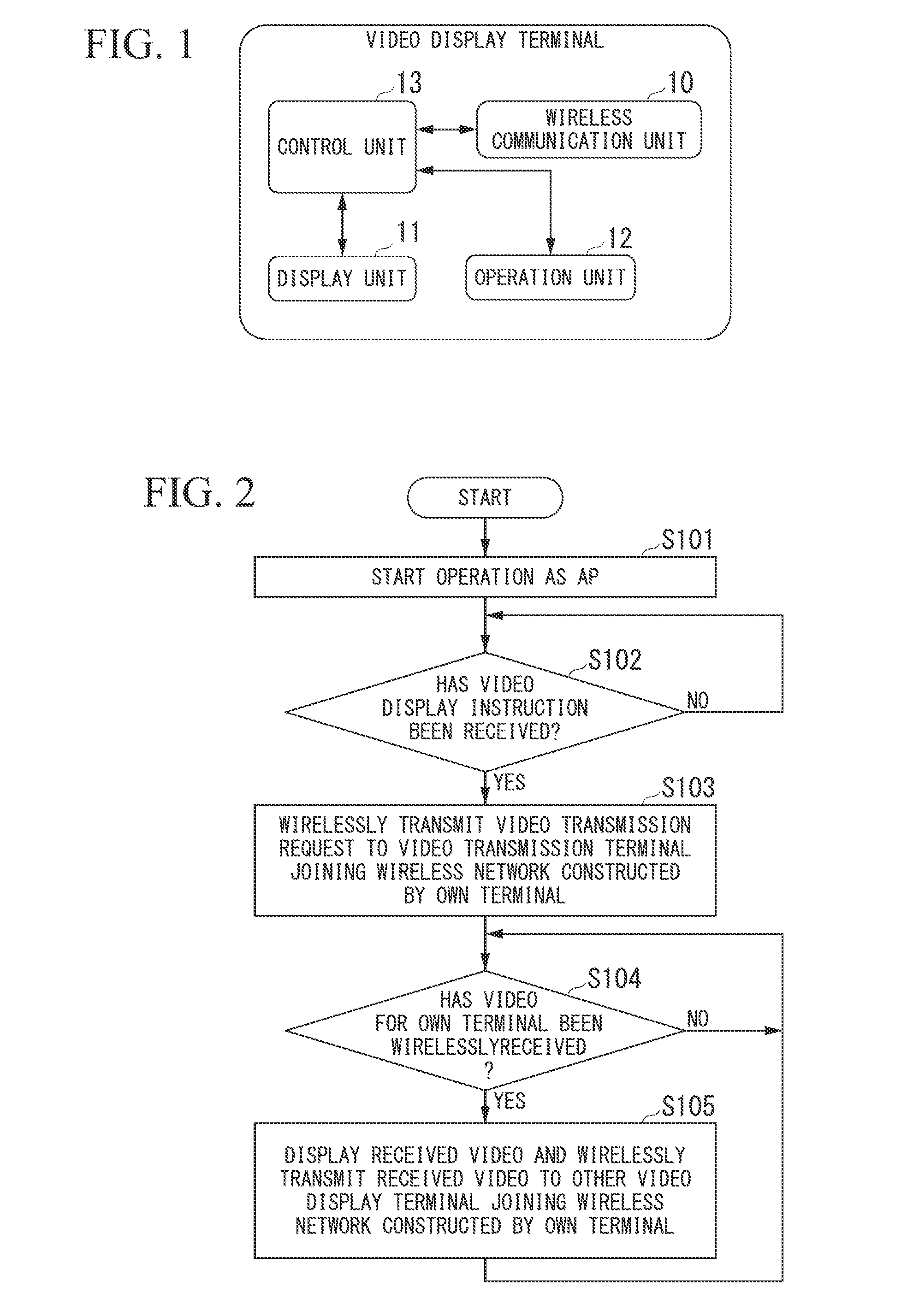
[0056]FIG. 1 illustrates a configuration of a video display terminal according to the first embodiment of the present invention. The video display terminal illustrated in FIG. 1 includes a wireless communication unit 10, a display unit 11, an operation unit 12, and a control unit 13.

[0057]The wireless communication unit 10 is a wireless communication interface, for example, a wireless communication module or a wireless communication device, configured to wirelessly communicate with another terminal. The display unit 11 is a display interface, for example, a display module or a display device, configured to display a video received by the wireless communication unit 10. The operation unit 12 is an operation interface, for example, an operation module or an operation device, configured to receive a user's operation. The control unit 13 controls each unit of the video display terminal. More specifically, if the operation unit 12 has received a video display instruction when its own ter...

second embodiment

[0072]Next, the second embodiment of the present invention will be described. FIG. 4 illustrates a configuration of a video transmission terminal according to this embodiment. The video transmission terminal illustrated in FIG. 4 includes a wireless communication unit 20, a storage unit 21, and a control unit 22.

[0073]The wireless communication unit 20 is a wireless communication interface, for example, a wireless communication module or a wireless communication device, configured to wirelessly communicate with another terminal. The storage unit 21 is a storage module, for example, a storage device, having a storage medium such as a memory or buffer for storing a video or various types of information. The storage unit 21 is not an essential configuration for obtaining an effect of reducing the degradation of throughput when the video is transmitted from the video transmission terminal without causing a disconnection of the network. The video transmission terminal may include the sto...

third embodiment

[0099]Next, the third embodiment of the present invention will be described. A configuration of a video display terminal according to this embodiment is the same as that illustrated in FIG. 1.

[0100]A configuration of a video transmission terminal according to this embodiment is the same as that illustrated in FIG. 4. In this embodiment, when the wireless communication unit 20 has wirelessly received a video transmission request from a second video display terminal establishing a video session, the control unit 22 causes a wireless communication unit 20 to wirelessly transmit transmission destination information to a first video display terminal along with a video for the first video display terminal which operates as an AP.

[0101]An operation of the video display terminal is the same as that illustrated in FIG. 5. FIG. 8 illustrates an operation of the video transmission terminal. Hereinafter, parts different from the operation illustrated in FIG. 6 will be described for the operatio...


PUM


Abstract

A video display terminal includes a wireless communication interface, a display interface, an operation interface, and a control unit. The control unit causes the wireless communication interface to wirelessly transmit a video transmission request to a video transmission terminal joining a wireless network constructed by the own video display terminal if the operation interface receives a video display instruction when the own video display terminal operates as an access point constructing the wireless network, causes the display interface to display a video for the own video display terminal wirelessly transmitted from the video transmission terminal in response to the video transmission request and wirelessly received by the wireless communication interface, and causes the wireless communication interface to wirelessly transmit the video for the own video display terminal to another video display terminal joining the wireless network constructed by the own video display terminal.

Description

BACKGROUND OF THE INVENTION[0001]1. Field of the Invention[0002]The present invention relates to a video display terminal, a video transmission terminal, a video communication system, a video display method, a video transmission method, and a computer-readable recording medium recording a program for performing video communication via a wireless network. Priority is claimed on Japanese Patent Application No. 2013-235040, filed Nov. 13, 2013, the content of which is incorporated herein by reference.[0003]2. Description of Related Art[0004]According to the speedup of a wireless local area network (LAN), the spread of quality of service (QoS), or the like, the number of opportunities to communicate a video between devices using the wireless LAN is increasing. Users demand high resolution and low compression (or non-compression) of a video and high quality of video communication in which a delay between a video source terminal and a video reproduction terminal is reduced. Thus, a data a...

Claims


Application Information

Patent Timeline
Patent Type & Authority Applications(United States)
IPC IPC(8): H04N21/4363H04N21/222H04N7/10
CPCH04N21/43637H04N21/2223H04N7/106H04N21/2347
Inventor SHIBUYA, KAZUYUKI
Owner OLYMPUS CORP
Why Eureka
Try Eureka