Component mounting system

Active Publication Date: 2015-05-21
PANASONIC INTELLECTUAL PROPERTY MANAGEMENT CO LTD
View PDF3 Cites 6 Cited by
  • Summary
  • Abstract
  • Description
  • Claims
  • Application Information

AI Technical Summary

Benefits of technology

[0009]According to aspects of the invention, a connection request is issued to one of the mounting machines selected by an operation on the screen of the portable operation terminal in which the display portion and the operation portion are integrated with each other. Upon reception of an acknowledgement from the mounting machine as the destination of the connection request, the portable operation terminal connects itself to the mounting machine. On the other hand, the selected mounting machine sends the acknowledgement of the connection request and connects itself to the portable operation terminal. In such a configuration,

Problems solved by technology

However, in the example described in JP-A-2013-030641, there is a problem relevant to safety as follows.
For this reason, misconnection may be incurred to connect the portable operation terminal to an unintended mounting machine other than the mounting machine which should be operated.
Even in the case where misconnection has occurred, it is not easy for the worker to sense t

Method used


Image

  • Component mounting system
  • Component mounting system
  • Component mounting system

Examples


Embodiment Construction

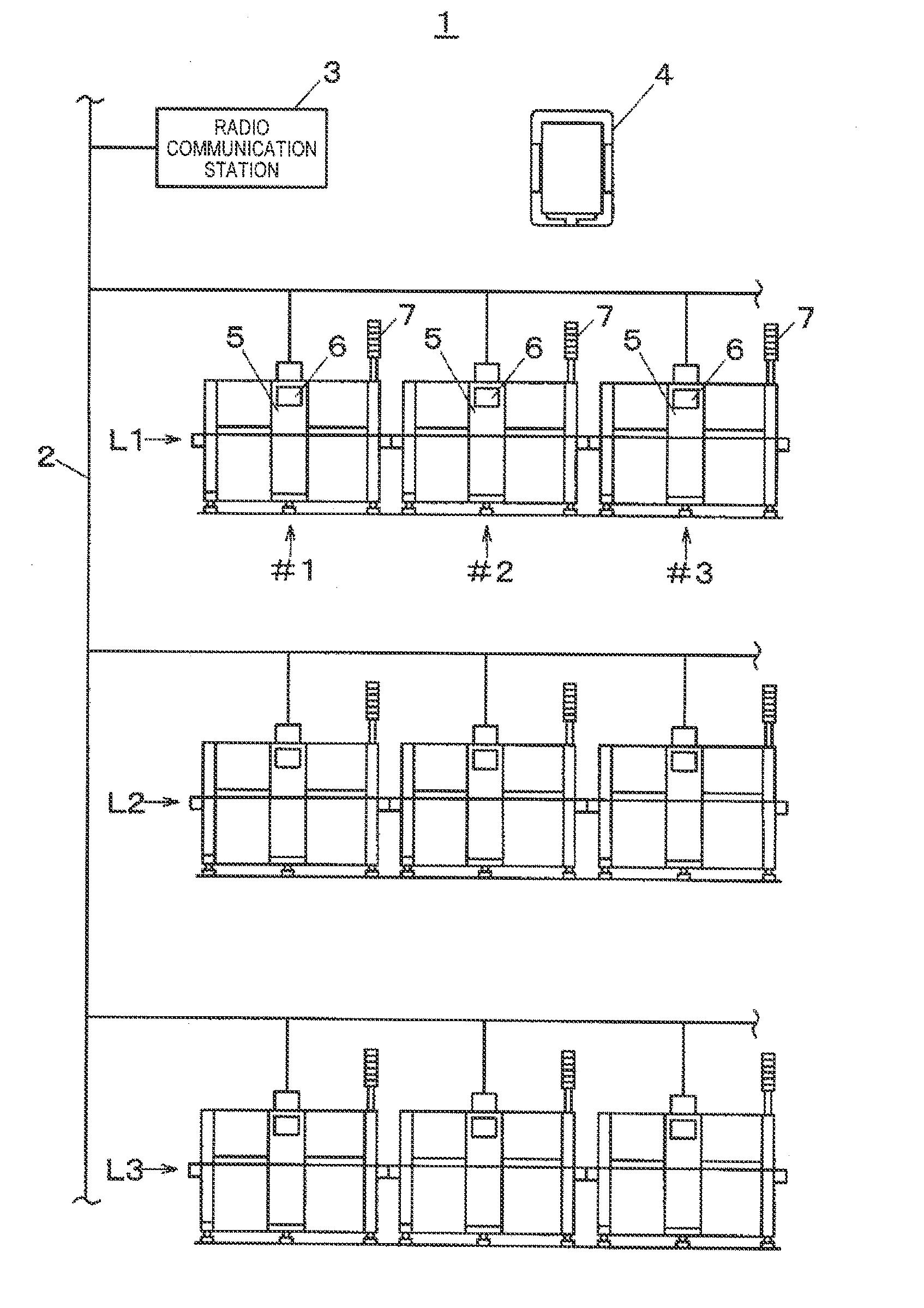
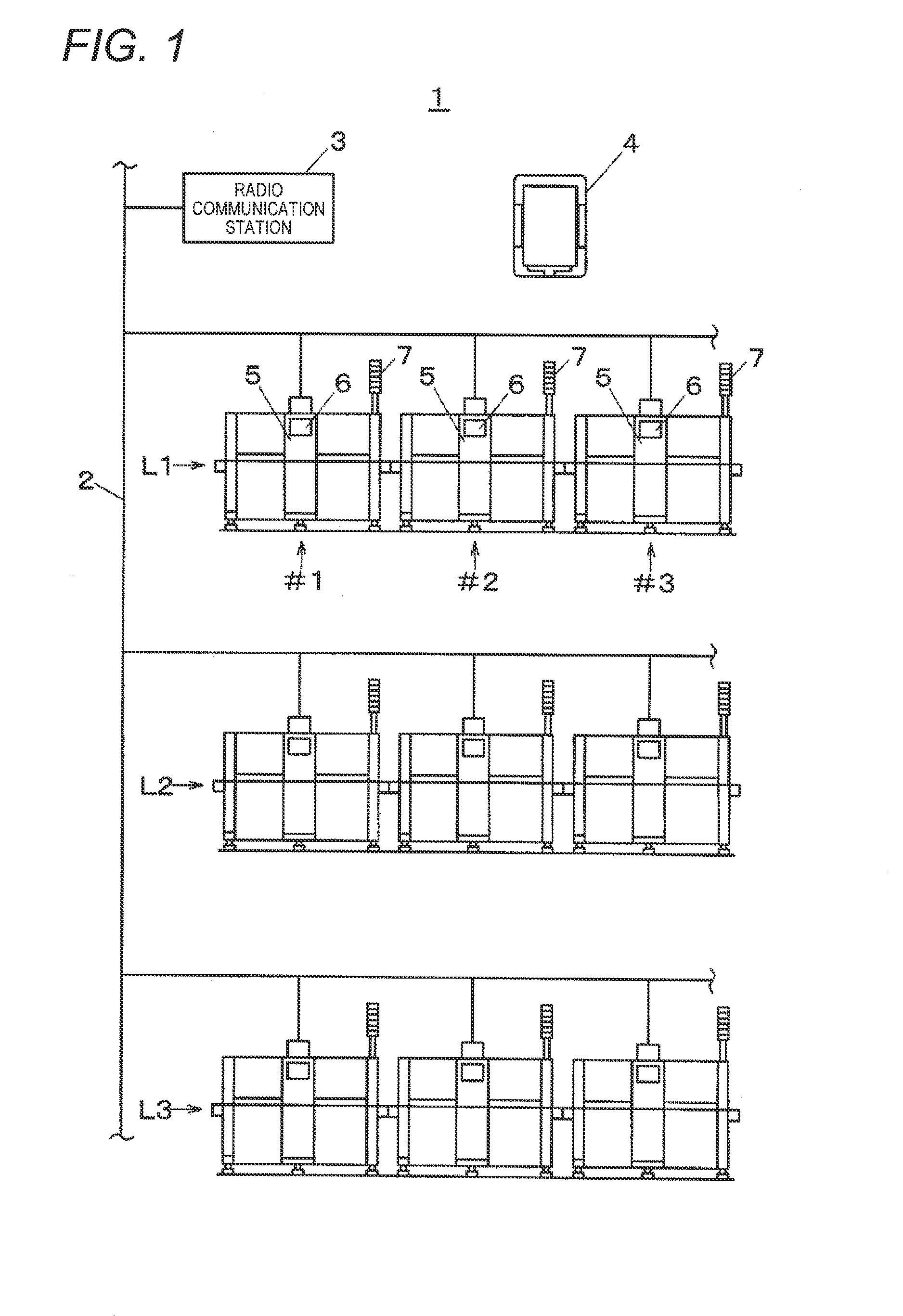
[0020]An embodiment of the invention will be described below with reference to the drawings. First, the configuration of a component mounting system 1 will be described with reference to FIG. 1. In FIG. 1, the component mounting system 1 has a function of mounting electronic components on substrates to manufacture mounted boards. The component mounting system 1 is constituted by a plurality of component mounting lines L1, L2, L3 . . . in each of which a plurality of pieces of component mounting equipment used for mounting components are linked. These pieces of component mounting equipment are connected to one another through a communication network 2. The communication network 2 includes a radio communication station 3. These pieces of component mounting equipment can be connected through radio communication to a tablet PC 4 serving as a portable operation terminal. Here, only the mounting machines #1, #2, #3 . . . for mounting electronic components on substrates in the component mo...


PUM


Abstract

In a component mounting system, a portable operation terminal is wirelessly connectable to mounting machines. The portable operation terminal includes: a processing portion which displays a screen allowing a worker to select one of the mounting machines to be connected to the portable operation terminal; and a terminal-side connection processing portion which issues a connection request to the selected mounting machine and which connects the portable operation terminal to the mounting machine upon reception of an acknowledgement from the mounting machine. The mounting machine includes: an equipment-side connection processing portion which connects the mounting machine to the portable operation terminal in response to the connection request, and a notification unit which notifies the worker of the fact that the mounting machine has been connected to the portable operation terminal, directly by at least one of sound and light.

Description

BACKGROUND[0001]1. Technical Field[0002]An aspect of the present invention relates to a component mounting system which includes mounting machines used for mounting components and a portable operation terminal wirelessly connectable to the mounting machines.[0003]2. Background Art[0004]There is a component mounting system in which mounting machines used for mounting components are linked to one another, as component mounting equipment for executing a work for mounting electronic components on substrates such as circuit substrates or liquid crystal substrates. Each of these mounting machines is provided with a control portion for controlling a component mounting mechanism which executes a component mounting work and an operation portion for performing a necessary operation input to the control portion. The operation portion includes a display panel displaying an operation screen, operation switches, etc. In the component mounting system, in place of a method in which the worker gains...

Claims


Application Information

Patent Timeline
IPC IPC(8): H05K13/08H05K3/30
CPCH05K3/301H05K13/08H05K13/0882Y10T29/53087G08B21/187
Inventor YOKOMAE, TAKAHIROMATSUO, NOBUYANISHINAKA, TERUAKI
Owner PANASONIC INTELLECTUAL PROPERTY MANAGEMENT CO LTD
Why Eureka
Try Eureka