Method for manufacturing flat pipe

Inactive Publication Date: 2015-05-21
HINO MOTORS LTD
View PDF2 Cites 2 Cited by
  • Summary
  • Abstract
  • Description
  • Claims
  • Application Information

AI Technical Summary

Benefits of technology

[0011]The method for manufacturing the flat pipe as mentioned in the above can exhibit excellent effects. A number of joints to be joined is reduced to one, which can substantially reduce workload in the troublesome joint joining work. Moreover, the manufacturing method can be conducted stepwise in a manufacturing-line work with a thin p

Problems solved by technology

Such structure with the plural heat-transfer pipes in parallel with each other in the shell has a problem that the heat exchanger as a whole b

Method used


Image

  • Method for manufacturing flat pipe
  • Method for manufacturing flat pipe
  • Method for manufacturing flat pipe

Examples


Embodiment Construction

[0019]An embodiment of the invention will be described in conjunction with the drawings.

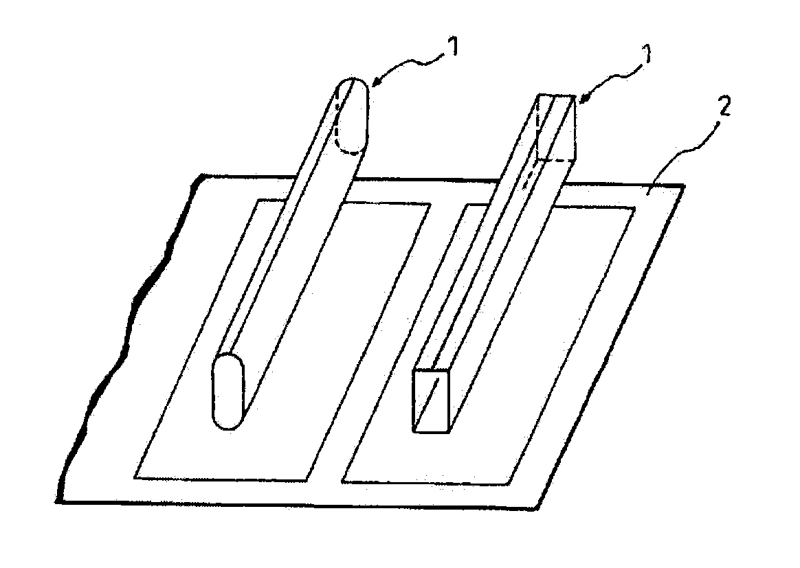
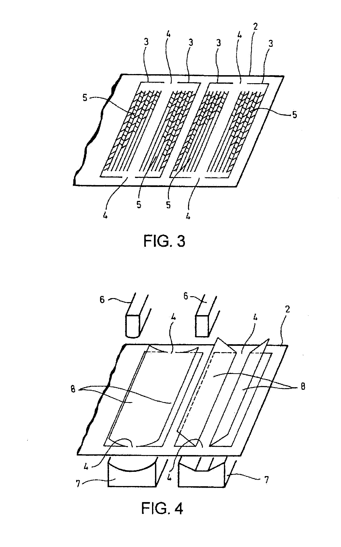
[0020]FIGS. 2-7 show the embodiment of the invention schematically showing a method for manufacturing a flat pipe 1 with concave-convex shapes on inner and outer surfaces. Though the flat pipe 1 appears firstly in FIG. 7 for a final step of the method, for explanation convenience the flat pipe is referred to together with its reference numeral early in description on initial steps while referring to FIG. 7.

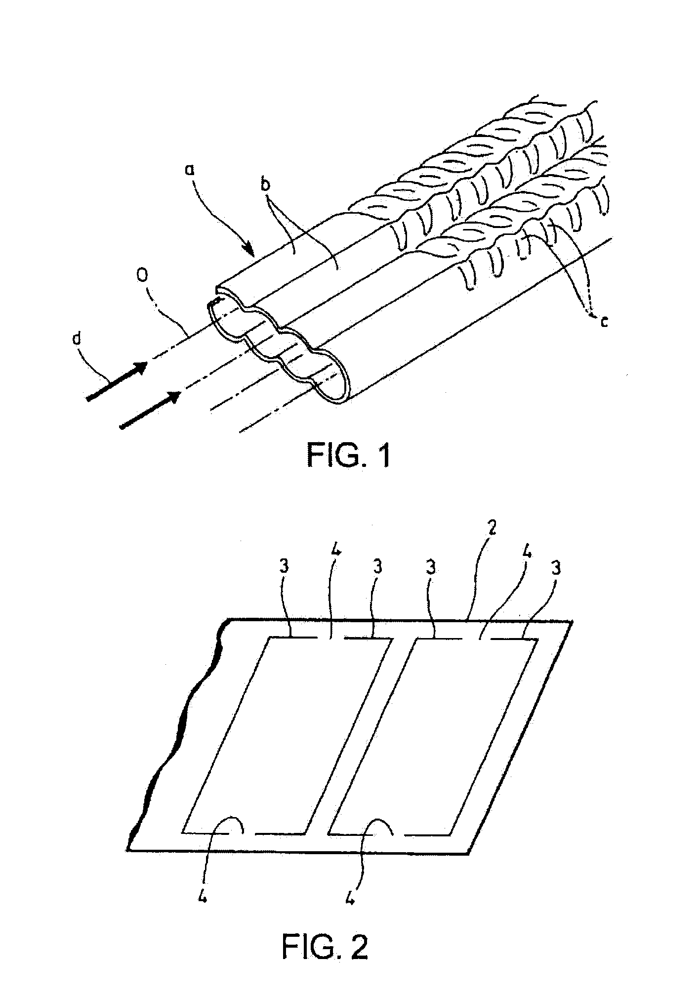
[0021]FIG. 2 shows a first step in the method for manufacturing the flat pipe according to the embodiment. In the first step, a metal thin plate 2 is punched out in an expanded shape of the flat pipe 1 (see FIG. 7) to provide incisions 3 with the expanded shape in the thin plate 2 such that the expanded shape of the flat pipe 1 has middle portions 4 (intermediate portions) widthwise of the expanded shape (laterally in FIG. 2; longitudinally of the thin plate 2) which are left uncut from the thi...


PUM

PropertyMeasurementUnit
Shapeaaaaaaaaaa

Abstract

A method for manufacturing a flat pipe 1 with concave-convex shapes on inner and outer surfaces includes making incisions with an expanded shape of the flat pipe 1 in a metal thin plate 2 such that intermediate portions 4 (middle portions) in the expanded shape of the flat pipe 1 widthwise of the expanded shape are left uncut from the thin plate 2, machining the concave-convex shapes in a range of the expanded shape of the flat pipe 1 and raising the expanded shape of the flat pipe 1 from the thin plate 2 as cut-and-raised pieces 8 with the uncut intermediate portions 4 in between, closing tips of the cut-and-raised pieces 8 together to form an overall shape of the flat pipe 2, and separating the uncut intermediate portions 4 from the thin plate 2 to obtain the flat pipe 1.

Description

TECHNICAL FIELD[0001]The present invention relates to a method for manufacturing a flat pipe.BACKGROUND ART[0002]For example, in a shell-and-tube heat exchanger or the like, a plurality of heat-transfer pipes are carried in a shell such that a primary medium flowing through the pipes are heat-exchanged with a secondary medium flowing through the shell. It has been already proposed, for example, in undermentioned Patent Literatures 1 and 2 that outer peripheries of the heat-transfer pipes are formed with spiral grooves which provide spiral protrusions, as inverse formations, on inner peripheries of the pipes to swirl the primary medium flowing through the pipes, thereby increasing contact frequency and contact distance of the primary medium to the inner peripheries of the pipes to enhance the heat exchange efficiency.[0003]Such structure with the plural heat-transfer pipes in parallel with each other in the shell has a problem that the heat exchanger as a whole becomes large in struc...

Claims


Application Information

Patent Timeline
IPC IPC(8): B21D5/16B21D28/02B21D35/00B21D53/04
CPCB21D5/16B21D35/002B21D28/02B21D53/04B21D5/015B21D53/08F28F1/02F28F1/426F28F2001/027B21D53/06F28F1/025F28F2255/08F28F2001/428B21D35/001B26D5/34
Inventor ISHIMORI, TAKASHIOKANO, MASAYUKI
Owner HINO MOTORS LTD
Why Eureka
Try Eureka