Antenna device and method for attaching the same

Active Publication Date: 2015-05-21
NEC CORP
View PDF7 Cites 222 Cited by
  • Summary
  • Abstract
  • Description
  • Claims
  • Application Information

AI Technical Summary

Benefits of technology

[0017]With the present invention, it is possible to provide an antenna device for which a cost is low and a strength characteris

Problems solved by technology

It is necessary in the parabolic antenna to strengthen an antenna mounting mechanism for mounting the parabolic antenna to the antenna attachment pole in order to improve a strength charact

Method used


Image

  • Antenna device and method for attaching the same
  • Antenna device and method for attaching the same
  • Antenna device and method for attaching the same

Examples


Example

Embodiment 1

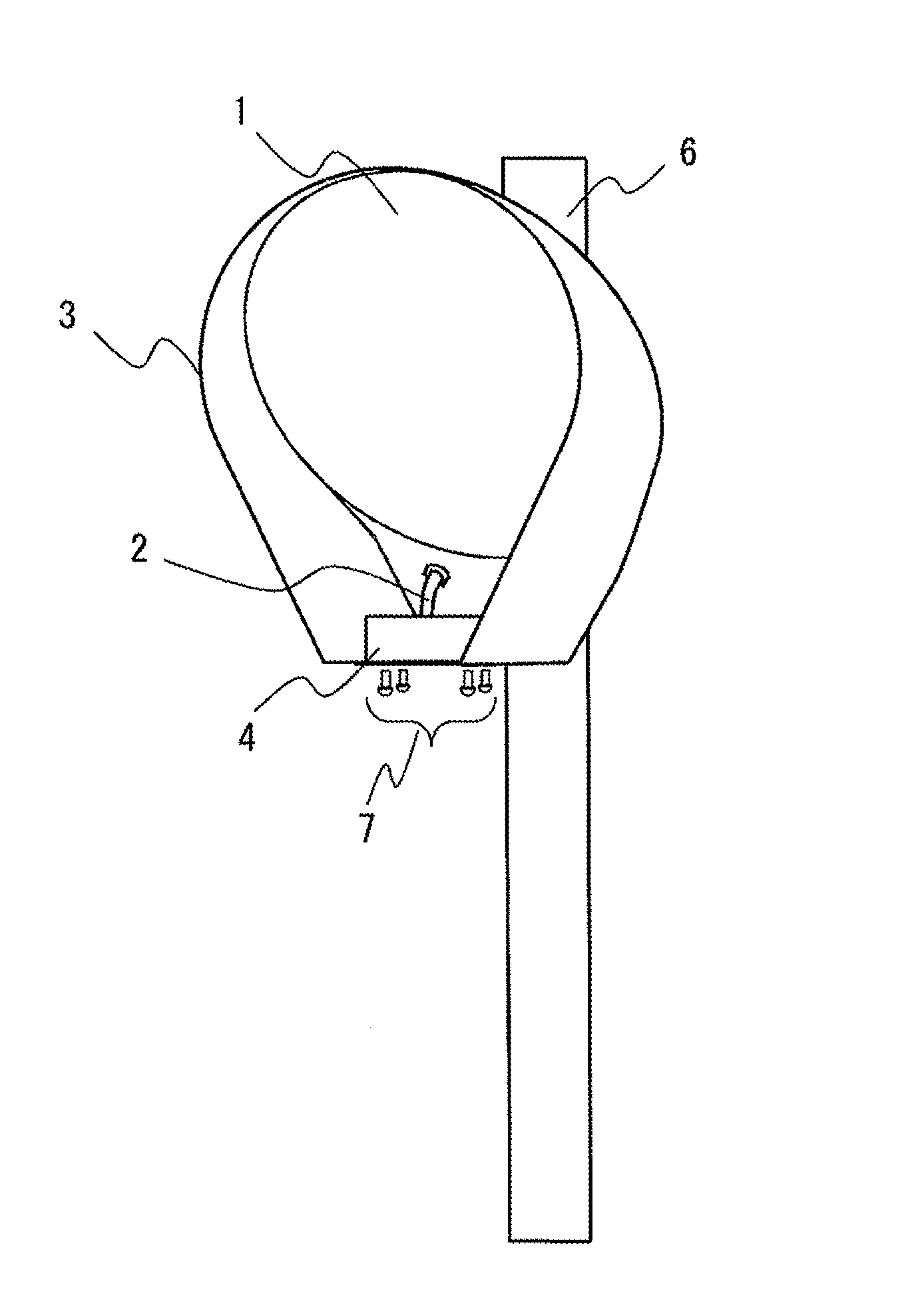
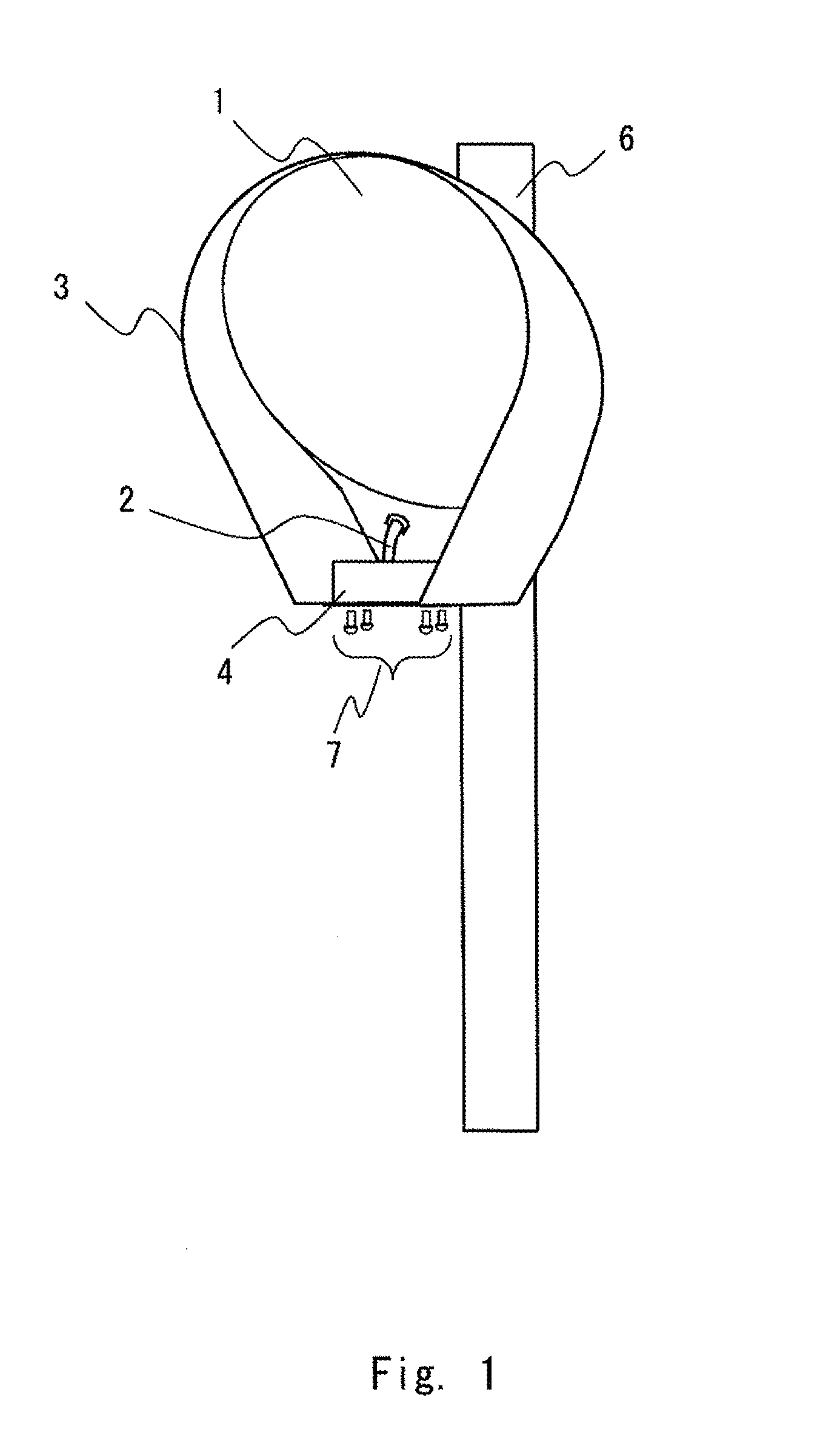
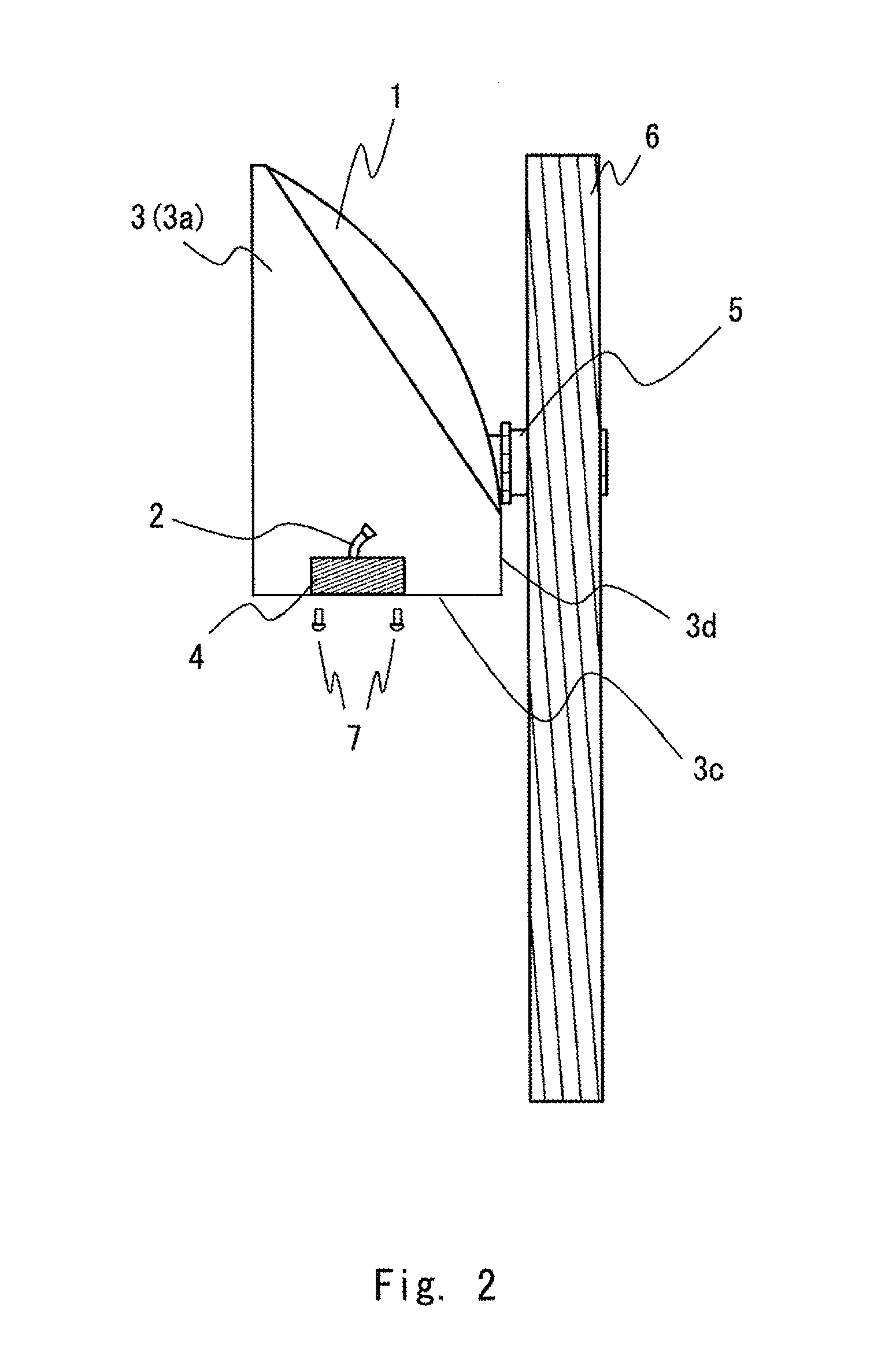
[0028]Hereinafter, the embodiments of the present invention will be explained with reference to drawings. FIGS. 1 to 3 show a perspective diagram, a side cross-sectional diagram, and an elevational diagram of an antenna device 10 according to the embodiment 1, respectively.

[0029]The antenna device 10 is specifically an offset parabolic antenna for a point-to-point communication line, and is provided with: an offset reflector 1; a primary radiator 2; a shroud 3; a radio device 4; and an antenna mounting mechanism 5.

[0030]The offset reflector 1 is a circular reflector, and reflects radio waves radiated by the primary radiator 2 in a front direction. An attachment angle of the offset reflector 1 is adjusted so as to reflect the radio waves radiated from the primary radiator 2 in a horizontal direction.

[0031]The primary radiator 2 is a horn antenna formed so that a cross-sectional area of an opening end becomes gradually wider. The primary radiator 2 is arranged outside an a...

Example

Embodiment 2

[0058]An antenna device according to the embodiment 2 is characterized in that a support (a support member) that supports a radio device is further installed inside the shroud 3. Hereinafter, the embodiment 2 will be explained in detail with reference to the drawings. However, explanation of a portion already explained in the embodiment 1 is partially omitted for clarity of the invention.

[0059]FIGS. 4 and 5 show a perspective diagram and a side cross-sectional diagram of an antenna device 20 according to the embodiment 2, respectively.

[0060]As can be seen from FIG. 5, in the antenna device 20, a support plate (support member) 21 is arranged inside the shroud 3. The support plate 21 supports the radio device 4, and is arranged at a lower inside of the shroud 3.

[0061]Here, the support plate 21 is fixed to the antenna mounting mechanism 5. In a method for fixing the support plate 21 to the antenna mounting mechanism 5, it may be fixed by attachment screws as shown in FIG. 5...

Example

Embodiment 3

[0071]An antenna device according to the embodiment 3 is characterized by using an ellipse-shaped offset reflector. Hereinafter, the above will be explained in detail with reference to the drawings. However, explanations of portions already explained in the embodiments 1 and 2 are partially omitted for clarity of the invention.

[0072]FIGS. 7 and 8 show a perspective diagram and an elevational diagram of an antenna device 30 according to the embodiment 3, respectively. As can be seen from FIGS. 7 and 8, the antenna device 30 is provided with an ellipse-shaped offset elliptical reflector 31.

[0073]As described above, a shape of a reflector is set to be elliptical, thereby an effect to enhance the low side lobe characteristic can be realized without increasing an antenna opening area, and also there is an effect of enhancing a strength characteristic of wind pressure load resistance.

[0074]Namely, in the embodiment 3, an antenna device becomes vertically long as a whole since ...


PUM

PropertyMeasurementUnit
Shapeaaaaaaaaaa

Abstract

An antenna device includes: a radio device for radio wave transmission; a primary radiator that has a function to radiates radio waves generated by the radio device; a parabolic reflector that reflects the radio waves radiated from the primary radiator; a shroud that shields against unnecessary radiation radio waves among the radio waves radiated from the primary radiator and reflected by the parabolic reflector; and an antenna mounting mechanism that fits the parabolic reflector to an antenna attachment pole. The shroud is arranged so as to cover at least a right and left of the parabolic reflector, the radio device and the primary radiator are arranged inside the shroud, and the antenna mounting mechanism fits the parabolic reflector to the antenna attachment pole so that the antenna attachment pole is located at a lateral center position of the parabolic reflector.

Description

TECHNICAL FIELD[0001]The present invention relates to an antenna device and a method for manufacturing the same, and particularly, to an offset parabolic antenna for a point-to-point communication line and a method for attaching the same.BACKGROUND ART[0002]As an antenna for a point-to-point communication line, a parabolic antenna has been widely used. Particularly when a severe low side lobe characteristic is required, an offset parabolic antenna may be used.[0003]In Patent Literature 1, an offset parabolic antenna is disclosed in which a worker can easily perform adjustment work of a polarization plane angle. The Patent Literature 1 discloses a method for offsetting a position of an antenna attachment pole with respect to a reflector lateral center, and mounting the offset parabolic antenna.[0004]While realization of the low side lobe characteristic is an important object in the parabolic antenna, it also becomes an important object to have a strength maintaining structure in cons...

Claims


Application Information

Patent Timeline
IPC IPC(8): H01Q1/12H01Q19/13H01Q1/52H01Q1/22
CPCH01Q1/1242H01Q1/526H01Q19/13H01Q1/22H01Q1/1228H01Q19/132Y10T29/49018
Inventor TAKAHASHI, YOSHIHIDE
Owner NEC CORP
Why Eureka
Try Eureka