Image processing apparatus, imaging apparatus and distance correction method

a technology of image processing apparatus and distance correction method, which is applied in the field of image processing apparatus, can solve the problems measurement errors, and distance estimation errors, and achieves the effect of increasing distance estimation errors, measuring errors, and calculating distance with relative accuracy

Active Publication Date: 2015-05-21
CANON KK
View PDF3 Cites 25 Cited by
  • Summary
  • Abstract
  • Description
  • Claims
  • Application Information

AI Technical Summary

Benefits of technology

[0009]In the case of a depth map estimated by the stereo method, the DFD method or the DFF method, it is known that distance estimation errors occur and measurement errors increase particularly in an area having little texture in a photographed image. If the size of a photographed object

Problems solved by technology

In the case of a depth map estimated by the stereo method, the DFD method or the DFF method, it is known that distance estimation errors occur and measurement errors increase particularly in an area having little texture in a photographed image.
If the size of a photographed object having texture is in the image, the texture of the object disappears in the photographed image, which

Method used


Image

  • Image processing apparatus, imaging apparatus and distance correction method
  • Image processing apparatus, imaging apparatus and distance correction method
  • Image processing apparatus, imaging apparatus and distance correction method

Examples


embodiment 1

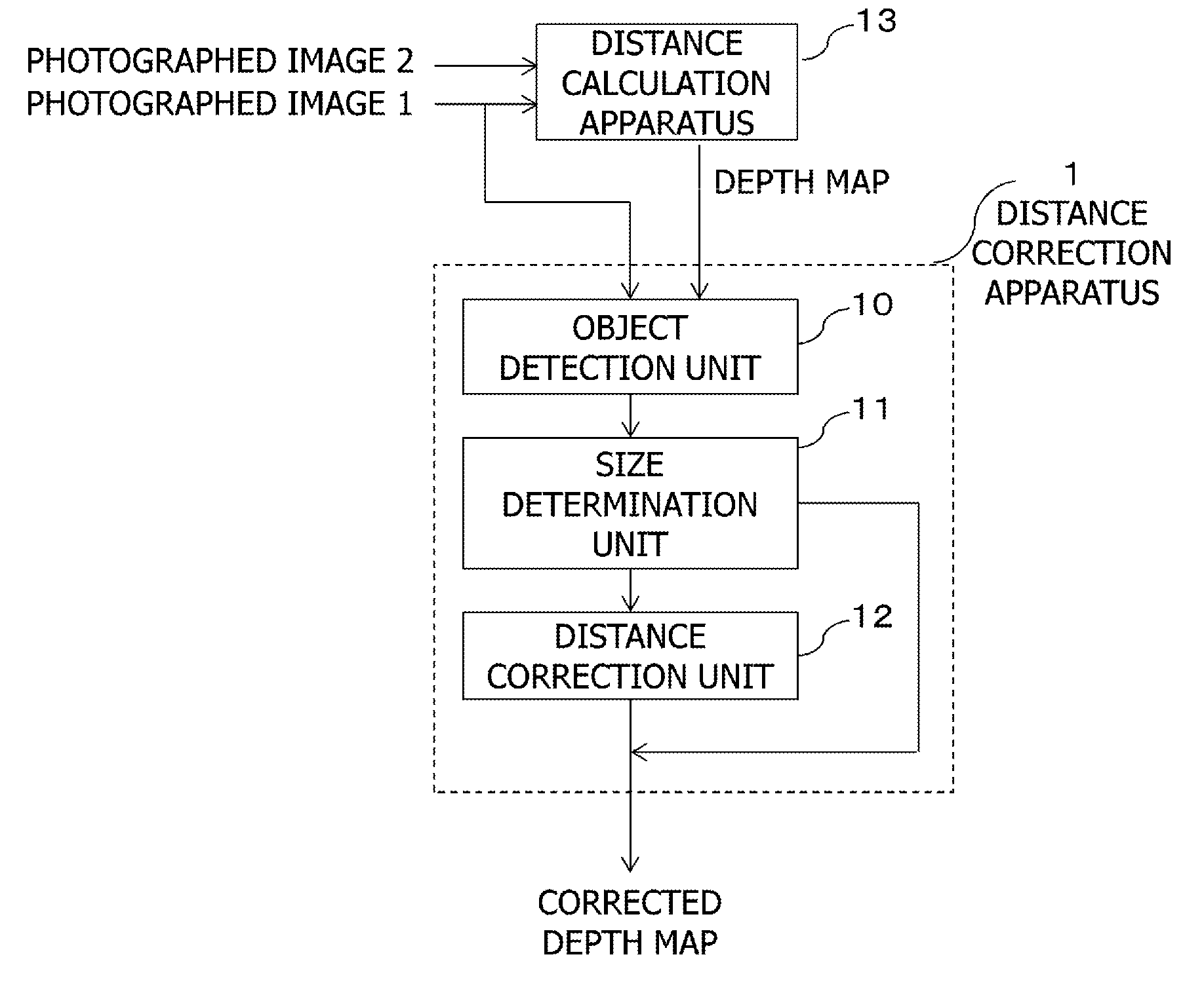
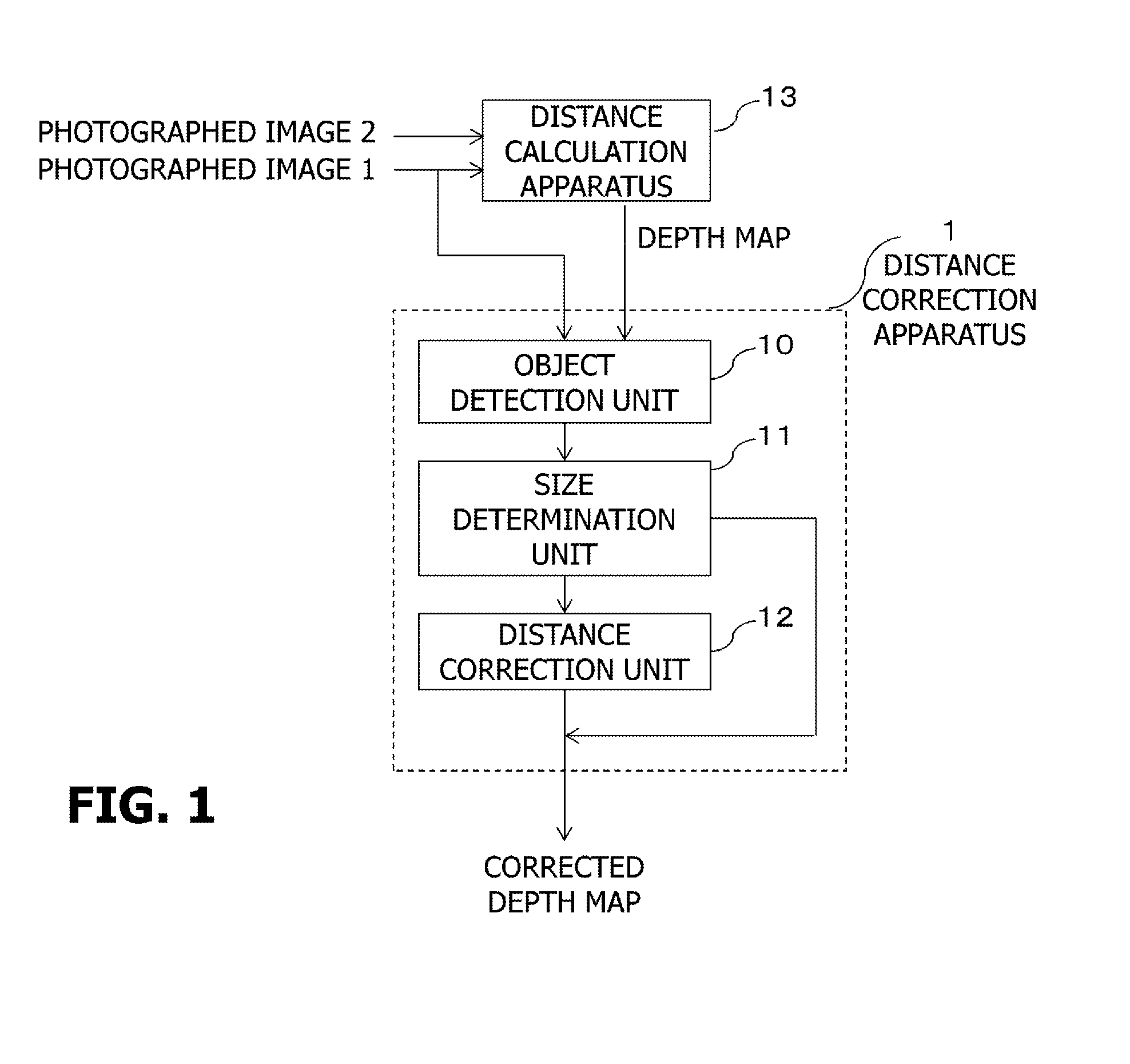
[0027]FIG. 1 is a block diagram depicting a configuration of an image processing apparatus according to Embodiment 1 of the present invention. The image processing apparatus is constituted by a distance calculation apparatus 13 and a distance correction apparatus 1. The distance correction apparatus 1 includes an object detection unit 10, a size determination unit 11, and a distance correction unit 12.

[0028]The distance calculation apparatus 13 is a functional unit that receives a plurality of images as an input, and generates a depth map (distance image) corresponding to the input images. A specific algorithm for the distance calculation can be arbitrary, but the distance (depth) correction processing to be described herein below can be suitably applied to a depth map generated by a passive distance calculation method. Examples of the passive distance calculation method are the stereo method, the DFD method and the DFF method. The stereo method receives a plurality of images having...

embodiment 2

[0049]FIG. 4 is a block diagram depicting a configuration of an image processing apparatus according to Embodiment 2 of the present invention. The image processing apparatus is constituted by a distance calculation apparatus 13 and a distance correction apparatus 2. The distance correction apparatus 2 includes a face detection unit 20, a size determination unit 11, an area determination unit 21, and a distance correction unit 12.

[0050]A difference of Embodiment 2 from Embodiment 1 is that the object detection is specifically for a human face. As a consequence, in this embodiment, the face detection unit 20 is disposed instead of the object detection unit 10. Another difference from Embodiment 1 is that the area determination unit 21, for calculating a representative value of the distances, is disposed. In this embodiment, the area for which the representative value of the distances is calculated (target areas) can be different from the area detected by the detection unit. Hereafter,...

embodiment 3

[0065]Embodiment 3 of the present invention will now be described. In Embodiment 1, the correction processing is performed by calculating a mean value or the like using all the estimated distance values in the object area. In Embodiment 2 as well, the correction processing is performed using the estimated distance values, excluding the singular values in the partial areas. In Embodiment 3 however, data other than the depth map is used, and the correction processing is performed using only highly reliable distances in the depth map. Hereafter mainly only the differences from Embodiment 1 will be described.

[0066]FIG. 8 is a block diagram depicting a configuration of an image processing apparatus according to Embodiment 3 of the present invention. The image processing apparatus is constituted by a distance calculation apparatus 13 and a distance correction apparatus 3. The distance correction apparatus 3 includes an object detection unit 10, a size determination unit 11, and a distance...


PUM


Abstract

An image processing apparatus for correcting, on the basis of an image and a depth map corresponding to the image, the depth map, includes: a detection unit that detects an object included in the image; a determination unit that determines whether a size of the object detected by the detection unit is a threshold or less; and a correction unit that corrects a distance in a target area which corresponds to an area of the object in the depth map, when the size of the detected object is the threshold or less.

Description

BACKGROUND OF THE INVENTION[0001]1. Field of the Invention[0002]The present invention relates to an image processing apparatus, and more particularly to a technique to correct a depth map.[0003]2. Description of the Related Art[0004]A technique to estimate distance using a plurality of captured images based on a stereo method, a depth from defocus (DFD) method, a depth from focus (DFF) method or the like and generate a depth map (also referred to as distance image) has been proposed. The stereo method is a technique to calculate a depth (also referred to as distance) based on a plurality of images photographed from different viewpoints. The DFD method and the DFF method are technique to calculate a distance based on a plurality of images of which photographing parameters are different. Distance images generated by these technique include errors, which lead to deterioration of quality of application that uses the depth maps.[0005]To solve this problem, Patent Literature 1 proposes a ...

Claims


Application Information

Patent Timeline
IPC IPC(8): G06T7/00G06T7/40
CPCG06T7/0059G06T2207/10012G06T7/40G06T7/0075G06T7/536G06T7/593G06T7/62G06T2207/30201
Inventor KOMATSU, SATORU
Owner CANON KK
Why Eureka
Try Eureka