Tracking of catheter from insertion point to heart using impedance measurements

Active Publication Date: 2015-05-21
BIOSENSE WEBSTER (ISRAEL) LTD
View PDF2 Cites 47 Cited by
  • Summary
  • Abstract
  • Description
  • Claims
  • Application Information

AI Technical Summary

Benefits of technology

The present invention provides a method and apparatus for accurately tracking a catheter over a volume of the body, from the point of insertion to the target. This is achieved by using a single enhanced impedance measuring system with multiple electroconductive body surface pads attached to the patient. The method involves measuring the characteristics of electrical currents passing through the body surface pads and using them to determine the position of the probe in real-time. This allows for the tracking of the actual path of the probe and ensures that it matches the intended path. The invention can be used in catheterization procedures and avoids the need for imaging the body using other modalities.

Problems solved by technology

In most situations, however, real-time three-dimensional imaging is not possible or desirable.

Method used


Image

  • Tracking of catheter from insertion point to heart using impedance measurements
  • Tracking of catheter from insertion point to heart using impedance measurements
  • Tracking of catheter from insertion point to heart using impedance measurements

Examples


first alternate embodiment

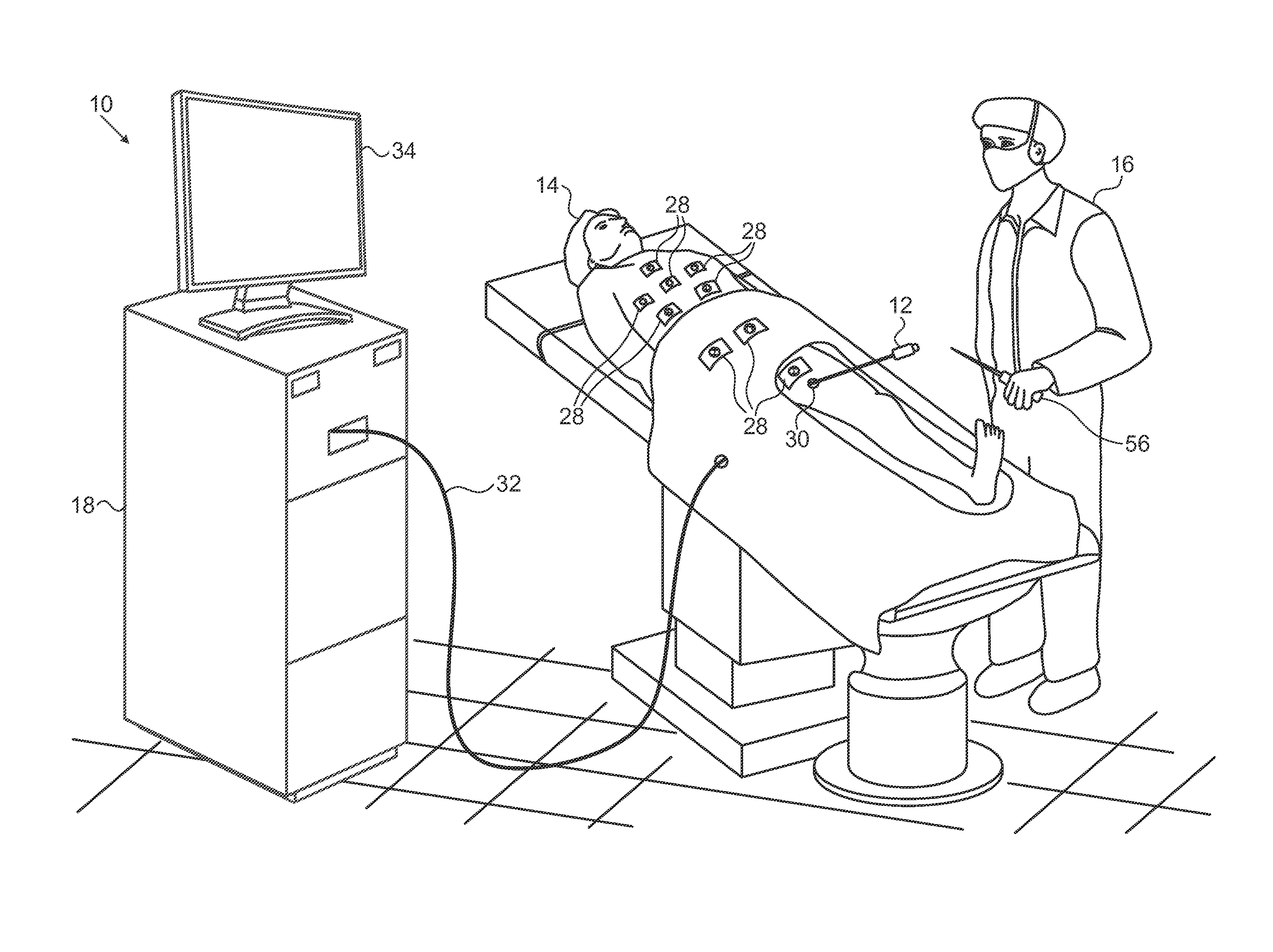
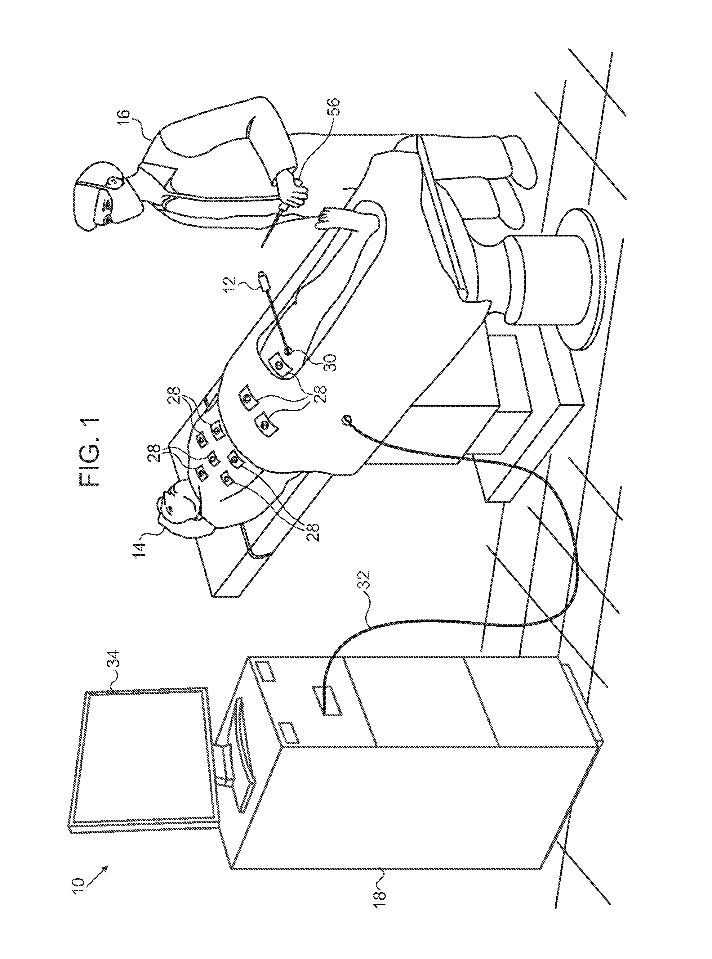
[0049]Referring again to FIG. 1, in order to further improve the accuracy of the ACL subsystem, an external handheld probe 56 containing an electromagnetic sensor is connected to the control unit 18. The system 10 for example the CARTO system, has well-known electromagnetic position tracking capabilities (EM tracking) that are based on readings from the magnetic sensor when the magnetic sensor is subjected to a magnetic field.

[0050]Reference is now made to FIG. 4, which is a schematic illustration of a hand-held probe 58 that may be used in the system shown in FIG. 1, in accordance with an embodiment of the invention. The probe 58 has a handle 60 at its proximal end to be grasped by a user. Distal portion 62 contains a magnetic sensor 64, which can be the sensor described in the above-noted U.S. Pat. No. 8,456,182 or in commonly assigned U.S. Patent Application Publication No. 2009 / 0221907, which is herein incorporated by reference. The probe 58 may communicate with control unit 18 ...

second alternate embodiment

[0052]Reference is now made to FIG. 5, which is a schematic view of the distal segment of the catheter 12 (FIG. 1), in accordance with an alternate embodiment of the invention. Distal segment 68 now contains a magnetic sensor 70, which can be the sensor described in the above-noted U.S. Pat. No. 8,456,182.

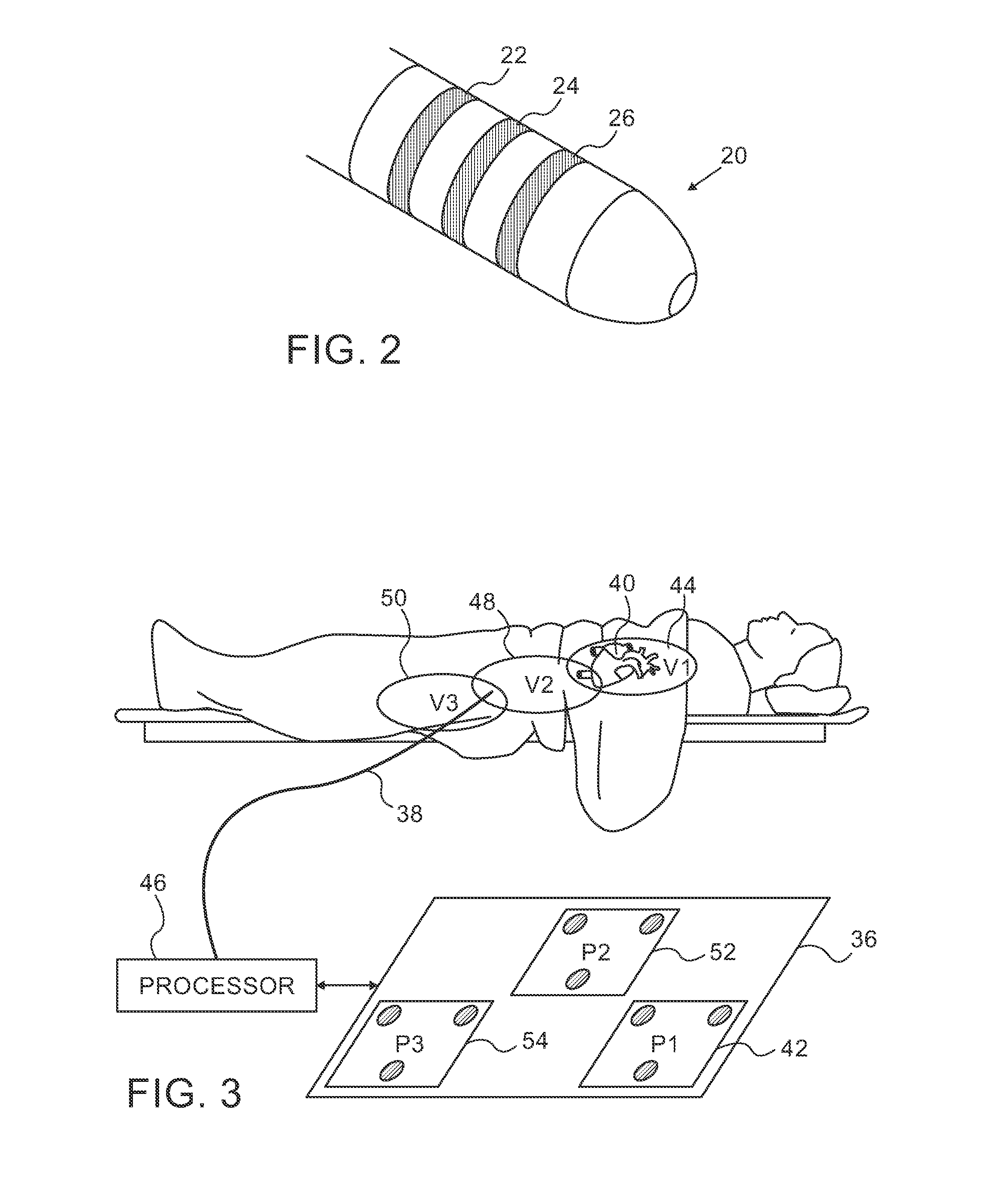
[0053]The system 10 (FIG. 1), for example the CARTO system, has well-known electromagnetic position tracking capabilities (EM tracking) that are based on readings from the magnetic sensor 70. Accuracy of the enhanced ACL subsystem as described above is improved by correlating the impedance measurements taken from the multi-location pad 36 (FIG. 3) with additional location information provided by the magnetic sensor 70. The ACL subsystem may be calibrated or trained to conform to the position as computed from the data supplied by the magnetic sensor 70. The EM tracking system typically provides the catheter tip location and orientation with an accuracy of approximately 1 mm and 1 de...

third alternate embodiment

[0054]In this embodiment, the multi-location pad 36 shown in FIG. 3 is omitted. Instead, individual pads are placed on the body surface as shown in FIG. 1. The pads 28 are distributed relatively sparsely over the insertion region, where location measurements computed by the impedances are less exacting. The pads are relatively more numerous and densely arranged in the region of the heart, where accuracy is more important. For example, a pad density over the heart of between 2 and 3 times the pad density away from the heart is suitable.


PUM


Abstract

A subject-specific skeletal model of a body is created, and an intended path of a catheter within the body is defined in the model. While the probe is inserted into the body electrical currents are passed through the body between at least one electrode in the probe and through respective electroconductive location pads that are disposed at a plurality of locations on the body surface along the intended path. Based on respective characteristics of the currents passing through the plurality of locations, position coordinates of the probe are iteratively determined. The actual path of the probe is tracked with reference to in the model using the iteratively determined position coordinates to determine whether the actual path corresponds to the intended path.

Description

BACKGROUND OF THE INVENTION[0001]1. Field of the Invention[0002]This invention relates to sensing the position of an object placed within a living body. More particularly, this invention relates to improvements in a catheter tracking system using impedance measurements.[0003]2. Description of the Related Art[0004]The meanings of certain acronyms and abbreviations used herein are given in Table 1.TABLE 1Acronyms and AbbreviationsACLActive Current LocalizationEMElectromagneticMRIMagnetic Resonance Imaging[0005]A wide range of medical procedures involve placing objects, such as sensors, tubes, catheters, dispensing devices, and implants, within the body. Real-time imaging methods are often used to assist doctors in visualizing the object and its surroundings during these procedures. In most situations, however, real-time three-dimensional imaging is not possible or desirable. Instead, systems for obtaining real-time spatial coordinates of the internal object are often utilized.[0006]U....

Claims


Application Information

Patent Timeline
IPC IPC(8): A61B5/06G01B7/00A61B5/00G01B7/004
CPCA61B5/063G01B7/004A61B5/6801A61B5/062A61B5/7425G01B7/003A61B5/6852G06T19/003G06T2210/41A61B2560/0223G16H50/50A61B34/20A61B2034/2051A61B5/743
Inventor BAR-TAL, MEIR
Owner BIOSENSE WEBSTER (ISRAEL) LTD
Why Eureka
Try Eureka