Electrical connector assembly with moveable contact elements

Inactive Publication Date: 2005-01-25
TYCO ELECTRONICS LOGISTICS AG (CH)
View PDF24 Cites 62 Cited by
  • Summary
  • Abstract
  • Description
  • Claims
  • Application Information

AI Technical Summary

Benefits of technology

Due to the arrangement of the contact elements along the surface of a contact support, they can be reliably arranged and held in predetermined positions without a problem. In addition thereto, when they are contacted with other contact elements, they have to be capable of withstanding no or just minimum mechanical loads. At any rate, possibly occurring mechanical loads do not entail a change of the contact element position or damage of the contact elements. This holds also for the event that the contact elements are of weak mechanic

Problems solved by technology

However, connectors of this type are not susceptible of reliable control, both in manufacture and in handling ther

Method used


Image

  • Electrical connector assembly with moveable contact elements
  • Electrical connector assembly with moveable contact elements
  • Electrical connector assembly with moveable contact elements

Examples


Example

The electrical connectors described hereinafter are circuit board connectors. However, it is to be pointed out already here that there is no restriction thereto. The special features of the electrical connectors described may also be applied to electrical connectors employed for other purposes.

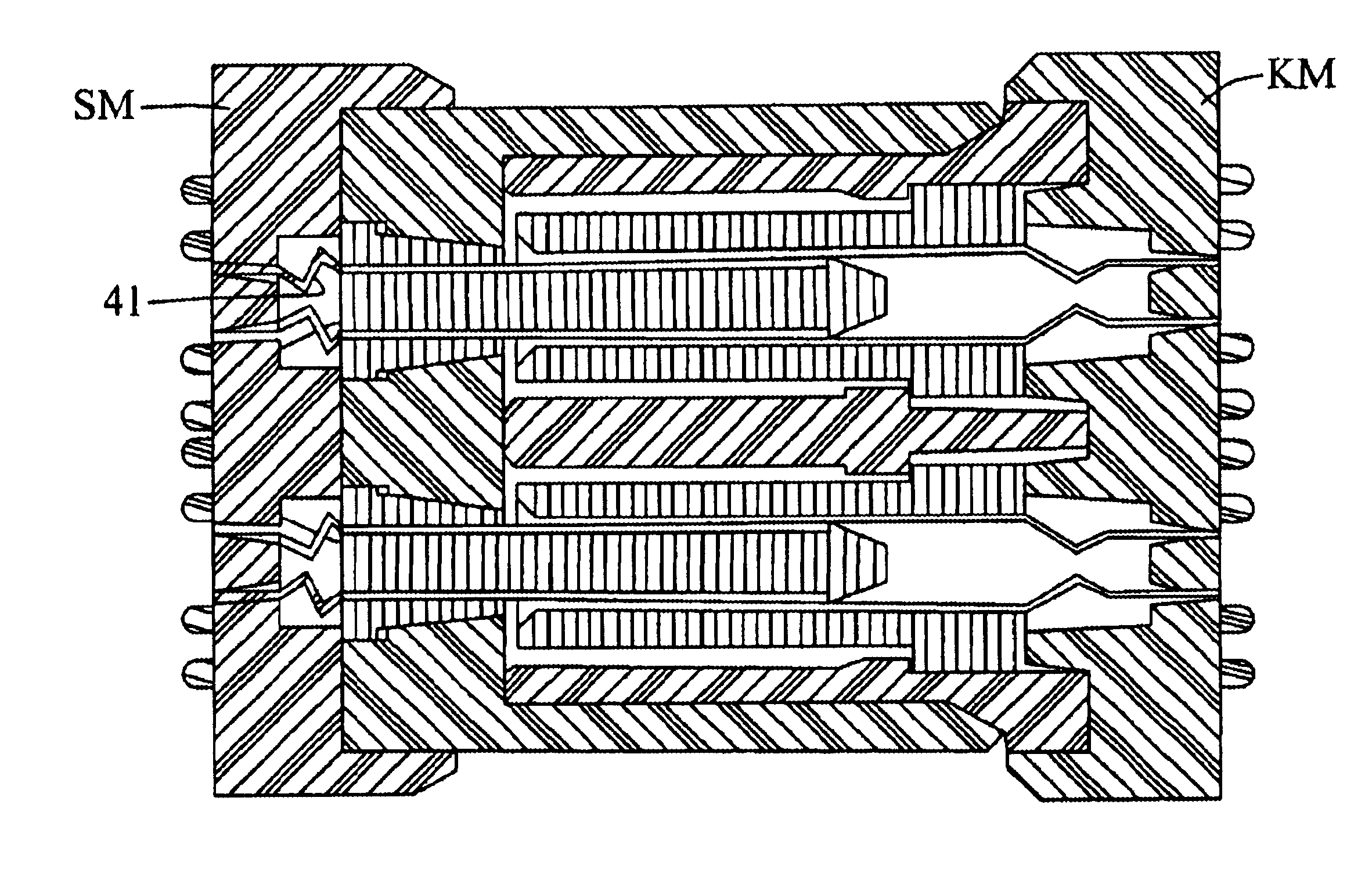
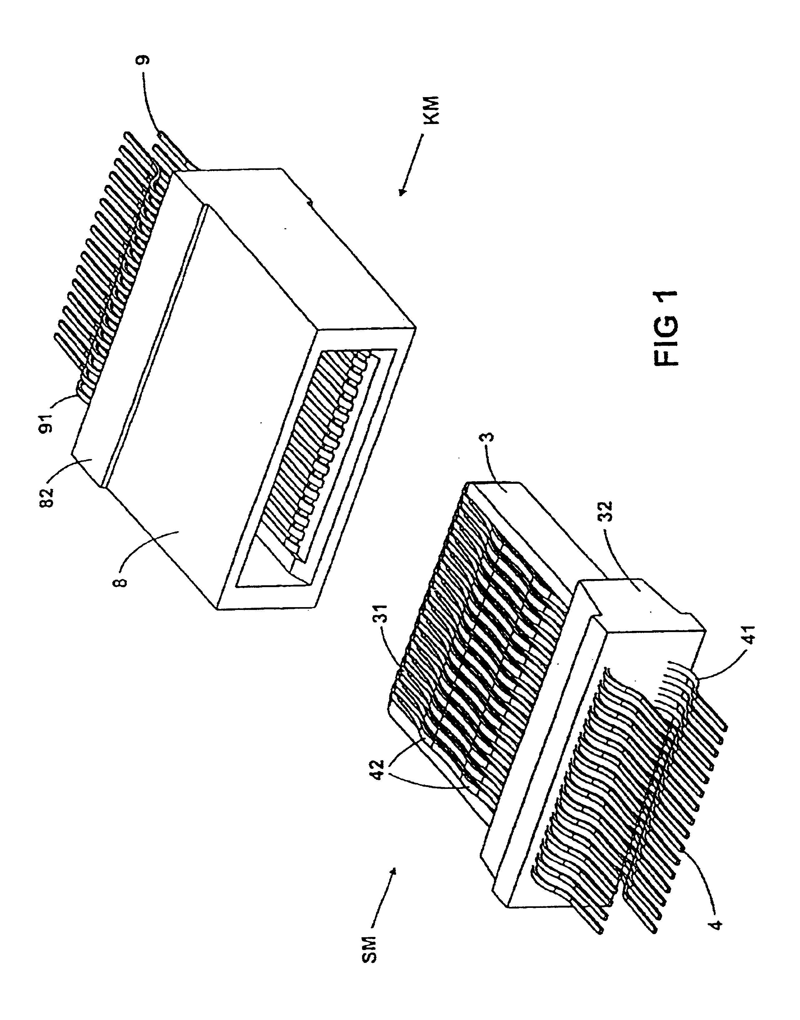
As is usual with pluggable connectors, an electrical connection is established by mating an electrical connector in the form of a plug and an electrical connector in the form of a coupling member.

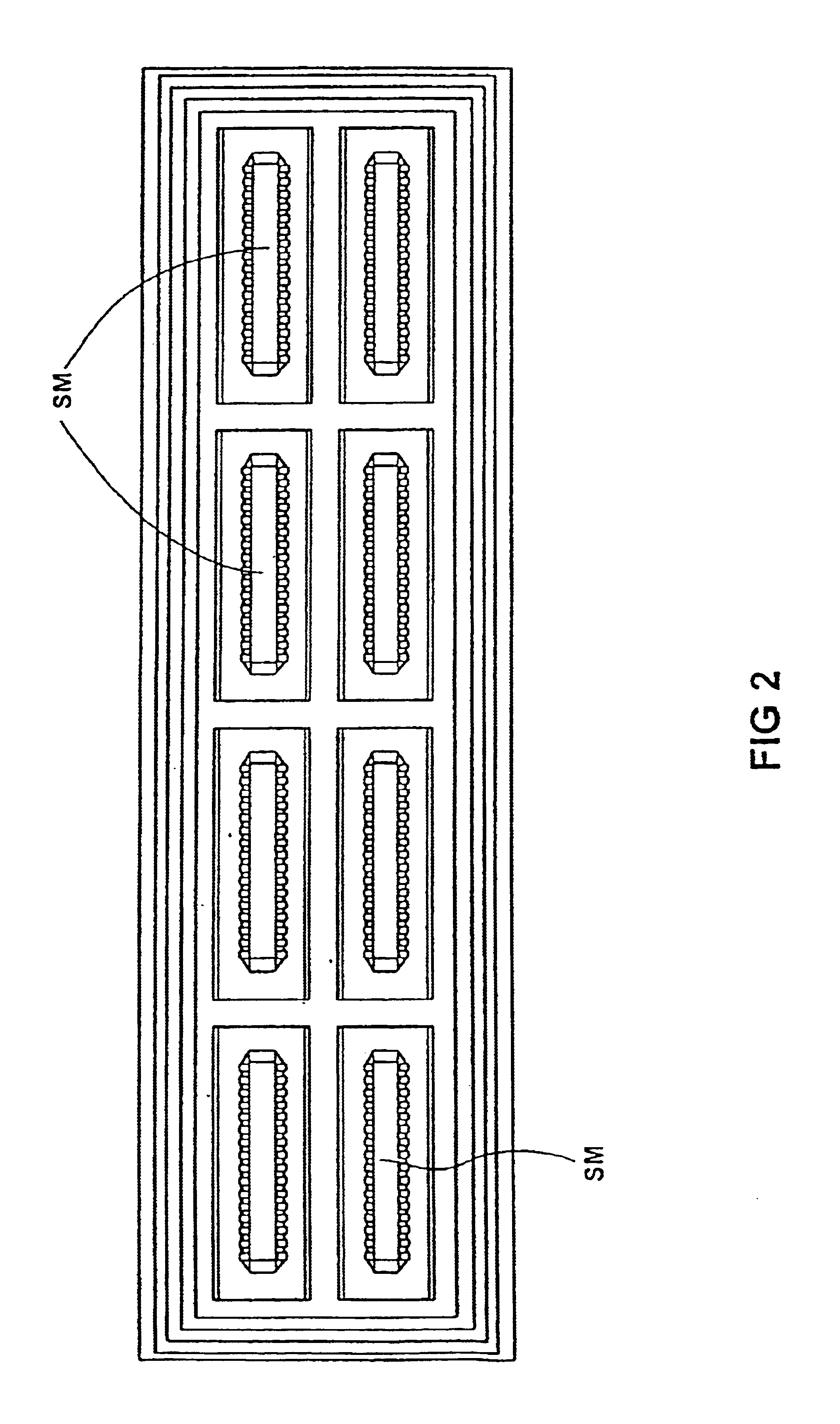
In the embodiment illustrated, the plug comprises a multiplicity of identical plug modules arranged side by side and / or on top of each other. The same holds for the coupling member. The latter comprises a multiplicity of identical coupling modules arranged side by side and / or on top of each other. However, the invention is not restricted to this. The plug and the coupling member may also contain only one module or a plurality of not identical modules.

A plug module and a coupling module are shown in a ...


PUM


Abstract

An electrical connector containing one or more connector modules, each having at least one contact support and a multiplicity of contact elements connected to the contact support in a non-releasable manner. The contact elements are connected to the contact supports by way of plastic material injection molded around part of the contact elements.

Description

BACKGROUND OF THE INVENTION1. The Field of the InventionThe present invention relates to a device according to the generic clause of claim 1, i.e. to an electrical connector comprising a multiplicity of contact elements.2. Technical BackgroundElectrical connectors have been known for many years in a multitude of forms.Due to the continuous increase in complexity and efficiency of electronic systems, there are also ever increasing requirements as to the electrical connections between the system components. In this regard, there is an increasing demand of electrical connectors which on the one hand operate reliably under all circumstances, i.e. also under high mechanical and electrical loads, and which on the other hand have as many contacts as possible while being as small as possible.There are already various electrical connectors known in which attempts have been made of fulfilling the requirements mentioned.In this context, the electrical connectors should be mentioned that are us...

Claims


Application Information

Patent Timeline
IPC IPC(8): H01R13/26H01R13/02H01R13/514H01R13/631H01R12/55H01R12/71
CPCH01R13/26H01R13/6315H01R13/514
Inventor SCHMIDT, HELGESANDER, REINHARD
Owner TYCO ELECTRONICS LOGISTICS AG (CH)
Why Eureka
Try Eureka