Wireless Charging Coil

a charging coil and wireless technology, applied in the direction of magnets, inductances, magnetic bodies, etc., can solve the problems of performance and manufacturing limitations, and achieve the effects of low profile, increased density, and thin thickness

Active Publication Date: 2015-05-28
A K STAMPING
View PDF6 Cites 103 Cited by
  • Summary
  • Abstract
  • Description
  • Claims
  • Application Information

AI Technical Summary

Benefits of technology

[0008]The present disclosure relates to wireless charging coils and methods for making thereof. More specifically, the present disclosure relates to a planar bifilar parallel-wound, series connected wireless charging coil. The coil has a thinner thickness (e.g., low profile), an increased density (e.g., high fill factor), and higher efficiency (e.g., lower resistance) than conventional wireless charging coils.

Problems solved by technology

Further, maximizing these goals can lead to performance and manufacturing limitations.

Method used


Image

  • Wireless Charging Coil
  • Wireless Charging Coil
  • Wireless Charging Coil

Examples


Embodiment Construction

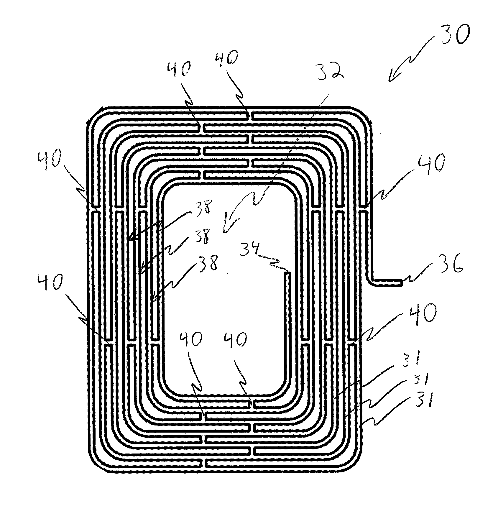
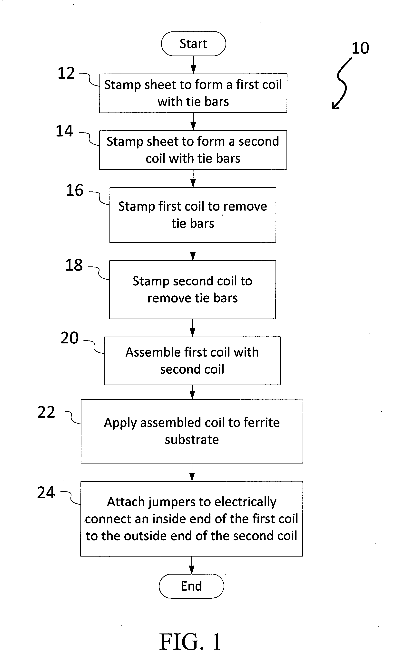
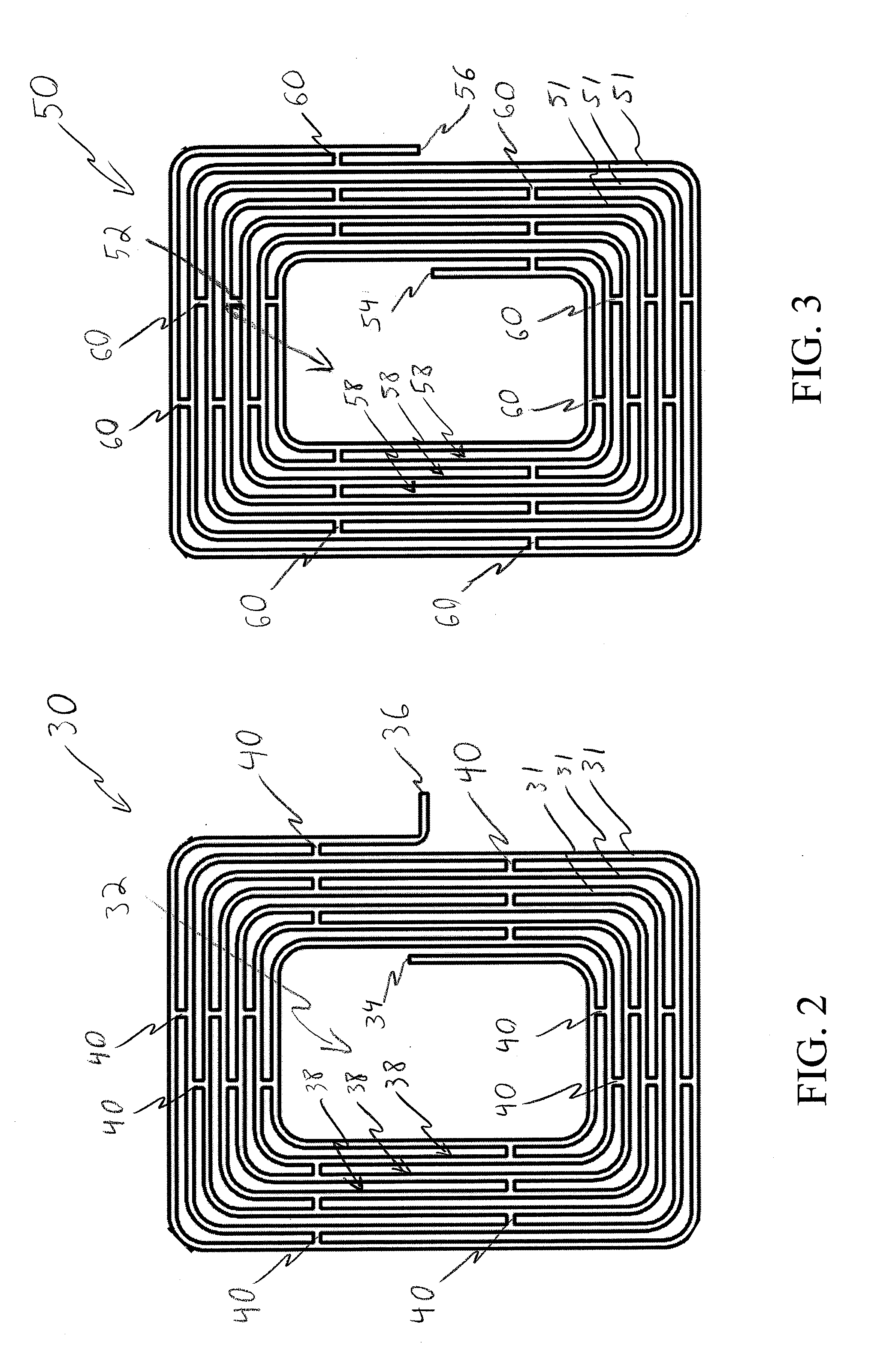
[0030]The present disclosure relates to a wireless charging coil and methods of making same. As discussed in more detail below in connection with FIGS. 1-7, the stamped metal wireless charging coil comprises a series of parallel traces connected in a bifilar fashion. In other words, the wireless charging coil includes first and second coils that are parallel, closely spaced, and connected in series such that the first and second coils have parallel currents. The first and second coils could be stacked or planar and connected in series and / or parallel to meet performance requirements (e.g., electrical requirements, power requirements, etc.). The wireless charging coil could be used in any battery powered device, particularly in mobile devices (e.g., smartphones, tablets, watches, etc.). The wireless charging coil can be made to be Qi compliant, but could be adjusted to comply with any wireless transfer protocol. A wireless charging coil with a greater amount of conductive material, s...


PUM

PropertyMeasurementUnit
ninety degree angleaaaaaaaaaa
resistanceaaaaaaaaaa

Abstract

A wireless charging coil is provided herein. The wireless charging coil comprising a first stamped coil having a first spiral trace, the first spiral trace defining a first space between windings, and a second stamped coil having a second spiral trace, the second spiral trace defining a second space between windings, wherein the first stamped coil and second stamped coil are planar to and interconnected with one another, such that the first stamped coil is positioned within the second space of the second stamped coil, and the second stamped coil is positioned within the first space of the first stamped coil.

Description

CROSS-REFERENCE TO RELATED APPLICATIONS[0001]This application claims priority to U.S. Provisional Patent Application No. 61 / 908,573 filed on Nov. 25, 2013, and U.S. Provisional Patent Application No. 62 / 004,587 filed on May 29, 2014, the entire disclosures of which are expressly incorporated herein by reference.BACKGROUND[0002]1. Field of the Disclosure[0003]The present disclosure relates to a wireless charging coil and methods for manufacturing thereof. More specifically, the present disclosure relates to a bifilar parallel wound, series connected wireless charging coil.[0004]2. Related Art[0005]Wireless power transfer is the transfer of electrical power from a base station (transferring power) to a mobile device (consuming power) through electromagnetic induction (inductive power) and / or resonant frequency method. Wireless power transfer is becoming increasingly popular in mobile devices, and particularly in smartphones. A popular standard for inductive charging technology is the ...

Claims


Application Information

Patent Timeline
Patent Type & Authority Applications(United States)
IPC IPC(8): H01F38/14H01F41/04
CPCH01F41/04H01F38/14H01F27/2847H01F27/2852H01F27/2871H04B5/0037Y10T29/49073H01F27/36H01F27/366H01F41/074
Inventor KURZ, ARTHURDUETSCH, BERNARDKURZ, JOSHUA
Owner A K STAMPING
Why Eureka
Try Eureka