Multi field-of-view multi sensor electro-optical fusion-zoom camera

a multi-sensor, electro-optical fusion technology, applied in the field of taking pictures with two or more cameras, can solve the problems of not providing for a system, not providing for the use of two separate cameras that can be independently mounted, and adding complexity in created wide field-of-view images, so as to achieve better resolution

Inactive Publication Date: 2015-05-28
BAE SYST INFORMATION & ELECTRONICS SYST INTERGRATION INC
View PDF22 Cites 60 Cited by
  • Summary
  • Abstract
  • Description
  • Claims
  • Application Information

AI Technical Summary

Benefits of technology

[0010]The preferred embodiment of the invention may include a system and method for creating an image. The system includes a first camera, a second camera, and a fusion processor. The first camera has a small field-of-view (FOV) and an optical line of sight (LOS). The second camera has a large FOV that is larger than the small FOV and the second camera has an optical LOS. The first camera and second camera are mounted so that the optical LOS of the first camera is parallel to the optical LOS of the second camera. The fusion processor fuses a second image captured by the second camera with a first image captured by the first camera to create a final image. The fused image has better resolution in a portion of the final image than in another portion of the final image.

Problems solved by technology

This system, however, requires the sensors to be located on a single substrate and does not provide for using two separate cameras that can be independently mounted.
However, it does not provide for a system that uses two different cameras that do not need to be moved to capture an image.
Additionally, the multiple cameras of this system are all pointed in different directions adding complexity in created wide field-of-view images.
An array of lenses adds undesirable
mechanical complexity and expense to this camera system.
These systems are complex in that they both need to stitch together images from cameras pointed in different directions which is not easy to accomplish.
For these reasons these prior art systems can be costly, time-consuming, and may not produce high quality images.

Method used


Image

  • Multi field-of-view multi sensor electro-optical fusion-zoom camera
  • Multi field-of-view multi sensor electro-optical fusion-zoom camera
  • Multi field-of-view multi sensor electro-optical fusion-zoom camera

Examples


Embodiment Construction

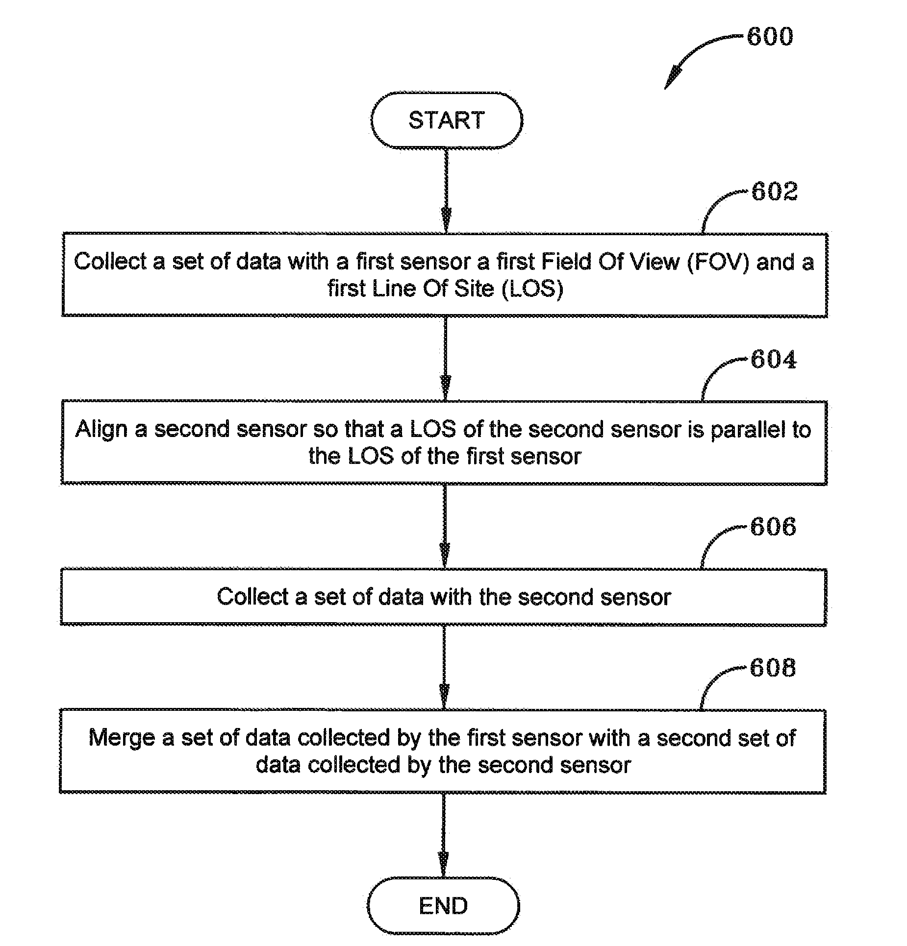
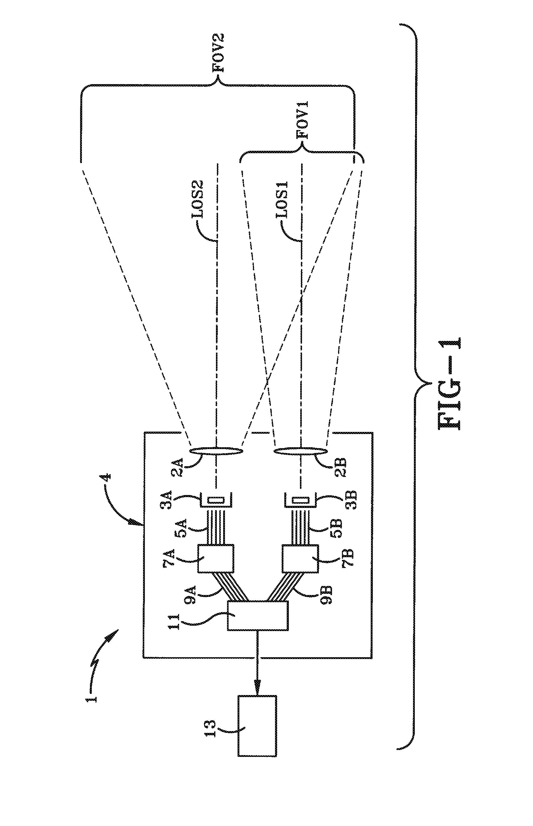
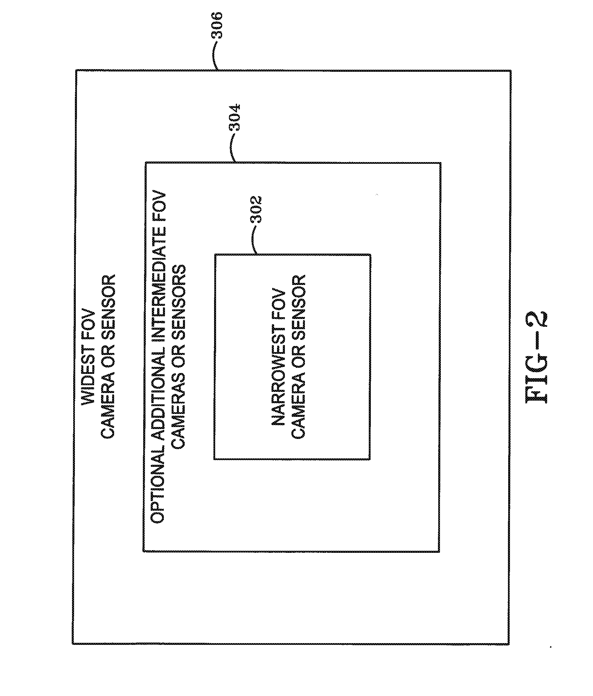
[0022]FIG. 1 illustrates the preferred embodiment of a camera system 1 that utilizes multiple co-located cameras each having a different field-of-view (FOV) FOV1, FOV2 and all of which point in the same direction. Camera 3A has a large FOV2 that is larger than the FOV1 of the second camera 3B. As seen in FIG. 1, the multiple FOV Cameras 3A-B are housed in a single housing 4. In other embodiments the cameras 3A-B are housed in separate housings. In the preferred embodiment, the cameras 3A-B are both optical cameras. However, in other configurations of the preferred embodiment, one or both of them can be infra-red (IR) cameras. In other embodiments, two or more cameras implementing the system 1 may be any combination of optical and IR cameras.

[0023]In the preferred embodiment, each camera 3A-B has a lens 2A, 2B. The optical Lines-Of-Sight (LOS) LOS1, LOS2 and optical axis of the cameras 3A, 3B are parallel. That is, each of the multiple cameras 3A, 3B are pointed in a common direction...


PUM


Abstract

A system and method for creating an image is presented. The system includes a first camera, a second camera, and a fusion processor. The first camera has a small field-of-view (FOV) and an optical line of sight (LOS). The second camera has a large FOV that is larger than the small FOV and the second camera has an optical LOS. The first camera and second camera are mounted so that the optical LOS of the first camera is parallel to the optical LOS of the second camera. The fusion processor fuses a second image captured by the second camera with a first image captured by the first camera. The fused image has better resolution in a fused portion of the fused image than in unfused portion of the fused image.

Description

BACKGROUND OF THE INVENTION[0001]1. Field of Invention[0002]The current invention relates generally to apparatus, systems and methods for taking pictures. More particularly, the apparatus, systems and methods relate to taking a picture with two or more cameras. Specifically, the apparatus, systems and methods provide for taking pictures with two or more cameras having multiple field-of-views and fusing their images into a single wide field-of-view image.[0003]2. Description of Related Art[0004]There have been prior attempts to use multiple sensors to detect an event. In particular, multiple cameras have been used to create a photograph that has a wider field-of-view (FOV) than can be captured using a single camera. For example, U.S. Pat. No. 6,771,208 describes a multi-sensor camera where each of the sensors are mounted onto a single substrate. Preferably the substrate is invar, a rigid metal that has been cured with respect to temperature so that its dimensions do not change with f...

Claims


Application Information

Patent Timeline
Patent Type & Authority Applications(United States)
IPC IPC(8): H04N5/262H04N5/232
CPCH04N5/23238H04N5/2621H04N5/272H04N23/45H04N23/951H04N23/11H04N23/698
Inventor MURPHY, ROBERT H.SAGAN, STEPHEN F.GERTSENSHTEYN, MICHAEL
Owner BAE SYST INFORMATION & ELECTRONICS SYST INTERGRATION INC
Why Eureka
Try Eureka