Methods and systems for a stop/start engine

a technology of stop/start engine and method, which is applied in the direction of engine starters, machines/engines, transportation and packaging, etc., can solve the problems of less than desired fuel reduction, less than desirable during some driving conditions, and annoyed drivers that the engine has stopped and is being restarted so quickly, so as to improve driver satisfaction, reduce aggravating the possibility of drivers, and improve the effect of driver satisfaction

Active Publication Date: 2015-05-28
FORD GLOBAL TECH LLC
View PDF7 Cites 16 Cited by
  • Summary
  • Abstract
  • Description
  • Claims
  • Application Information

AI Technical Summary

Benefits of technology

[0004]By allowing a driver to communicate to an engine stop / start controller via application of vehicle brakes, it may be possible to reduce the possibility of aggravating the driver during conditions where the driver may have more information than the vehicle engine controller regarding whether or not conditions are desirable for automatically stopping the engine. For example, a driver of a vehicle may notice that traffic lights for opposing traffic are about to change and give right of way to the driver. The driver may apply vehicle brakes in a prescribed manner that allows the driver to communicate with the automatic engine stop controller so that automatic engine stopping is inhibited in response to the driver applying vehicle brakes. As a result, the vehicle may accelerate in a more timely manner when automatic engine stopping is inhibited, thereby improving driver satisfaction.
[0005]The present description may provide several advantages. In particular, the approach may improve driver satisfaction. Additionally, the approach may save fuel when fuel consumption may be increased by stopping and engine and restarting the engine shortly thereafter. Further, the approach may provide the driver improved vehicle control as compared to other systems where the driver cannot communicate with the engine stop controller.

Problems solved by technology

However, if the engine is restarted immediately after it is stopped, the fuel reduction may be less than desired.
Further, the driver may be annoyed that the engine has stopped and is being restarted so quickly after being stopped.
Thus, automatically stopping an engine may conserve fuel, but it may also be less than desirable during some driving conditions.
However, there may be conditions when the driver wishes to override the engine stop functionality only once, or desires to override the engine stop feature without looking away from the vehicle's route to locate and active the switch.
Additionally, the approach may save fuel when fuel consumption may be increased by stopping and engine and restarting the engine shortly thereafter.

Method used


Image

  • Methods and systems for a stop/start engine
  • Methods and systems for a stop/start engine
  • Methods and systems for a stop/start engine

Examples


Embodiment Construction

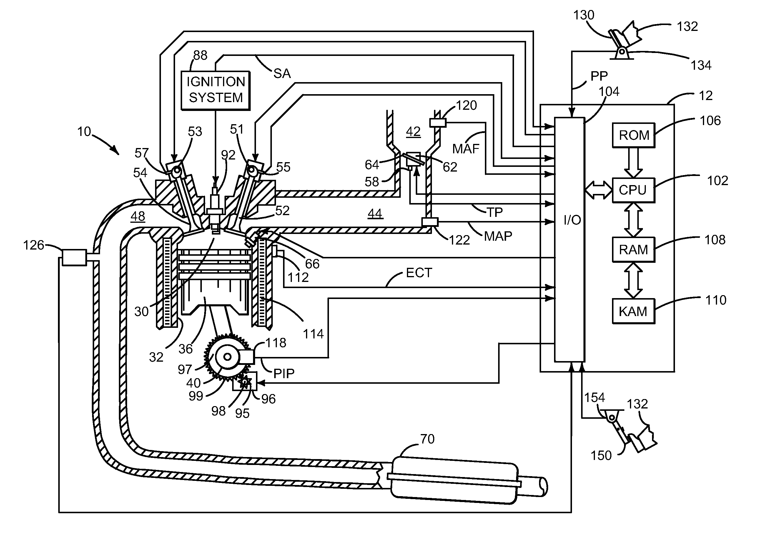
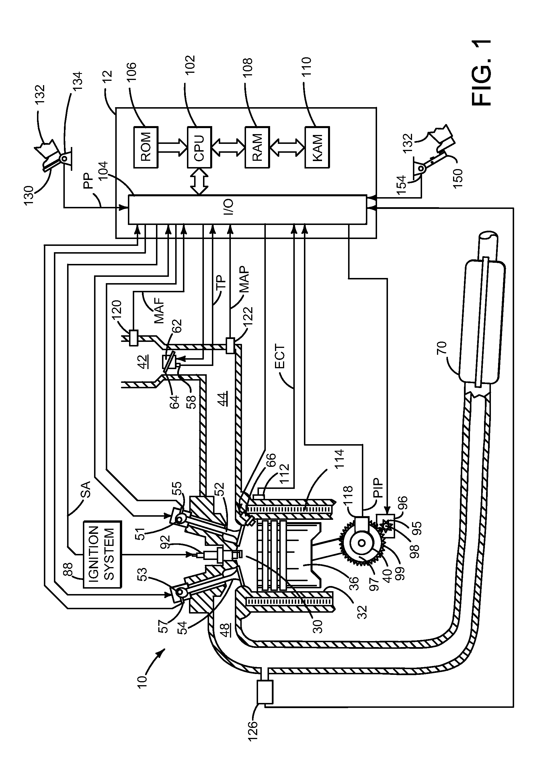
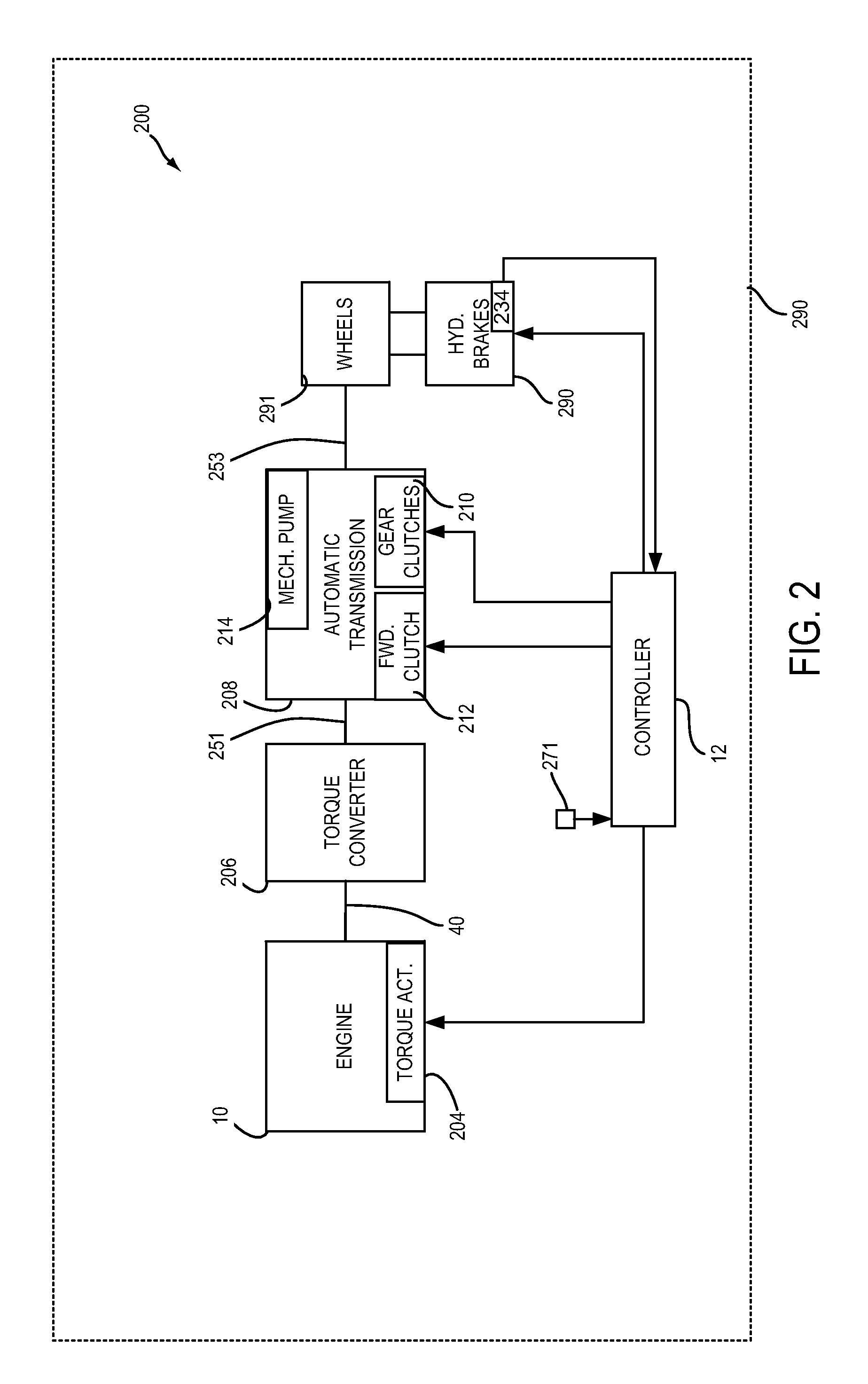
[0014]The present description is related to controlling operation of an engine that may be automatically stopped and started in a vehicle. The engine may be a sole source of torque for propelling the vehicle. Alternatively, the vehicle may include an engine and a motor that both supply torque to propel the vehicle. FIG. 1 shows an example engine system. The engine may be part of a vehicle driveline as is shown in FIG. 2. The engine may restart, automatically stop, or be prevented from being automatically stopped as shown in the engine operating sequence shown in FIG. 3. Vehicle brake system conditions illustrated in FIGS. 4 and 5 may be the basis for judging whether or not to automatically stop and / or start an engine. The method of FIG. 6 may operate an engine and driveline according to FIGS. 1 and 2 to provide the operating sequence shown in FIG. 3.

[0015]Referring to FIG. 1, internal combustion engine 10, comprising a plurality of cylinders, one cylinder of which is shown in FIG. 1...


PUM


Abstract

Systems and methods for improving operation of a vehicle are presented. In one example, automatic engine stopping is inhibited in response to a driver communicating a desire to not automatically stop an engine. The driver communicates intentions to allow or inhibit automatic engine stopping via a brake pedal.

Description

FIELD[0001]The present description relates to a system and methods for improving vehicle drivability and driver controls. The systems and methods may be particularly useful for engines that may be frequently stopped and restarted to conserve fuel.BACKGROUND AND SUMMARY[0002]An engine of a vehicle may be automatically stopped without a driver providing input to a device that has a sole purpose or function of stopping engine rotation so that fuel may be conserved (e.g., engine stop / start devices). Fuel may be conserved when the engine is automatically stopped since the engine does not consume fuel when it is not operating. However, if the engine is restarted immediately after it is stopped, the fuel reduction may be less than desired. Further, the driver may be annoyed that the engine has stopped and is being restarted so quickly after being stopped. Thus, automatically stopping an engine may conserve fuel, but it may also be less than desirable during some driving conditions. Present...

Claims


Application Information

Patent Timeline
Patent Type & Authority Applications(United States)
IPC IPC(8): B60W10/184B60W10/06
CPCB60W10/06B60W10/184B60R16/0231B60W10/18B60W30/18109B60W2710/18B60W2710/06B60W2510/18B60W30/18018F02N11/0822B60W2540/12F02N2200/102Y02T10/40
Inventor LYON, PETER MITCHELLDAME, ANDREW CLEMENTKUECHLER, PETER DOUGLASDONA, ALAN ROBERT
Owner FORD GLOBAL TECH LLC
Why Eureka
Try Eureka