Aircraft fuel tank inerting arrangement

a fuel tank and arrangement technology, applied in the direction of water supply installation, transportation and packaging, mechanical equipment, etc., can solve the problems of limiting the lifetime of the air separation module, lack of control of the arrangement, and more oxygen depletion, so as to reduce the amount of ozone and reduce the gas temperature

Inactive Publication Date: 2015-06-04
AIRBUS OPERATIONS LTD
View PDF8 Cites 5 Cited by
  • Summary
  • Abstract
  • Description
  • Claims
  • Application Information

AI Technical Summary

Benefits of technology

[0020]The aircraft fuel tank inerting arrangement optionally comprises an ozone reduction module upstream of the oxygen remover. Oxygen removers may be adversely affected by ozone and it is therefore desirable to reduce the amount of ozone entering the oxygen remover.
[0021]The aircraft fuel tank inerting arrangement may optionally comprise a gas cooler located upstream of the oxygen remover. Such coolers are preferable, especially if the gas introduced into the aircraft fuel tank inerting arrangement is at an elevated temperature (gas taken from an engine may be at a pre-cooling temperature of about 350° C. which, if not cooled, would have an adverse effect on an oxygen remover). The gas cooler may be operable to reduce gas temperature by at least 50° C., optionally by at least 100° C., optionally by at least 150° C., optionally by at least 200° C. and optionally by at least 200° C.

Problems solved by technology

Such an arrangement lacks control and more oxygen-depleted air than necessary may be supplied to a fuel tank.
This may limit the lifetime of the air separation module.

Method used


Image

  • Aircraft fuel tank inerting arrangement
  • Aircraft fuel tank inerting arrangement
  • Aircraft fuel tank inerting arrangement

Examples


Embodiment Construction

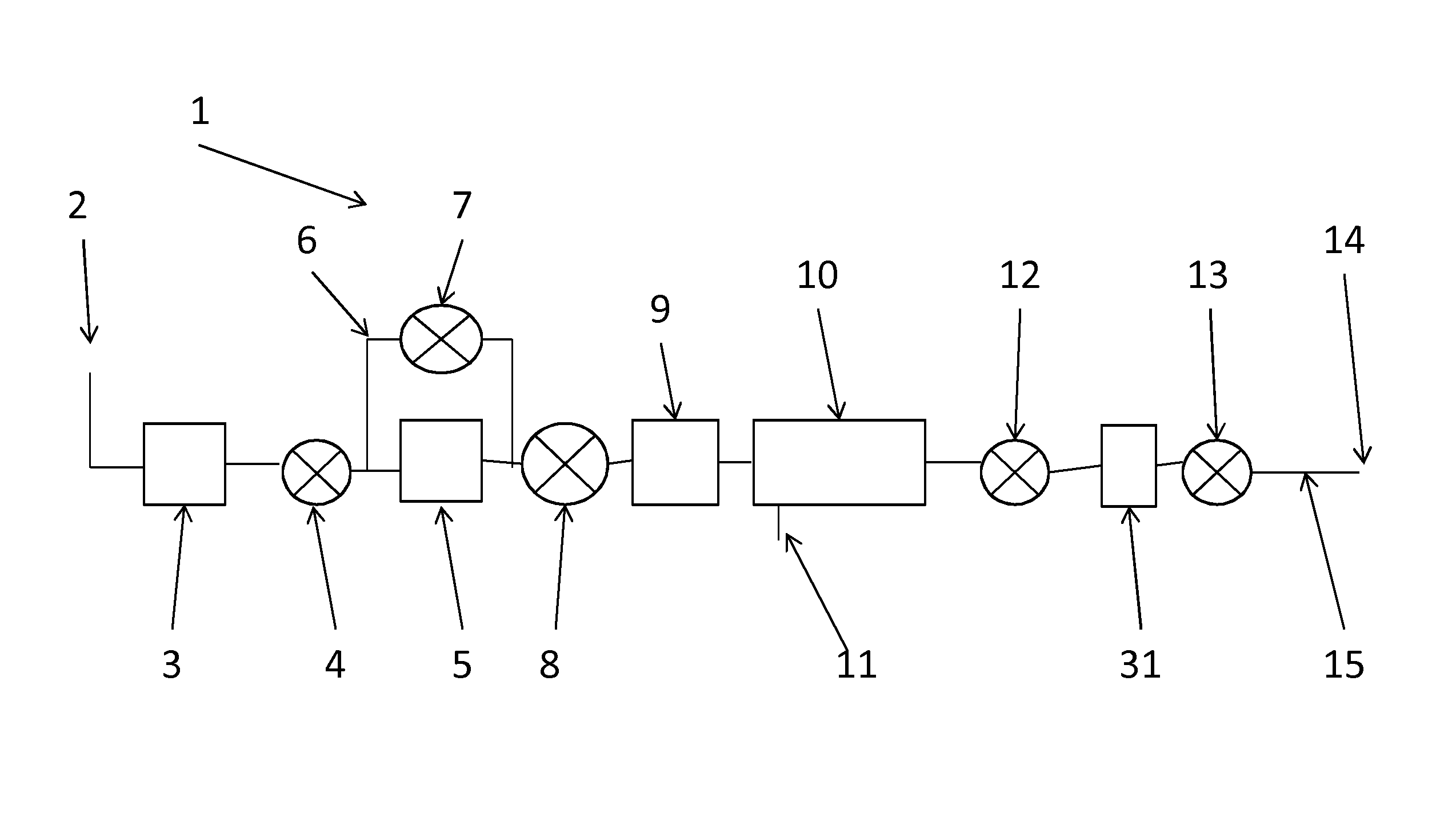
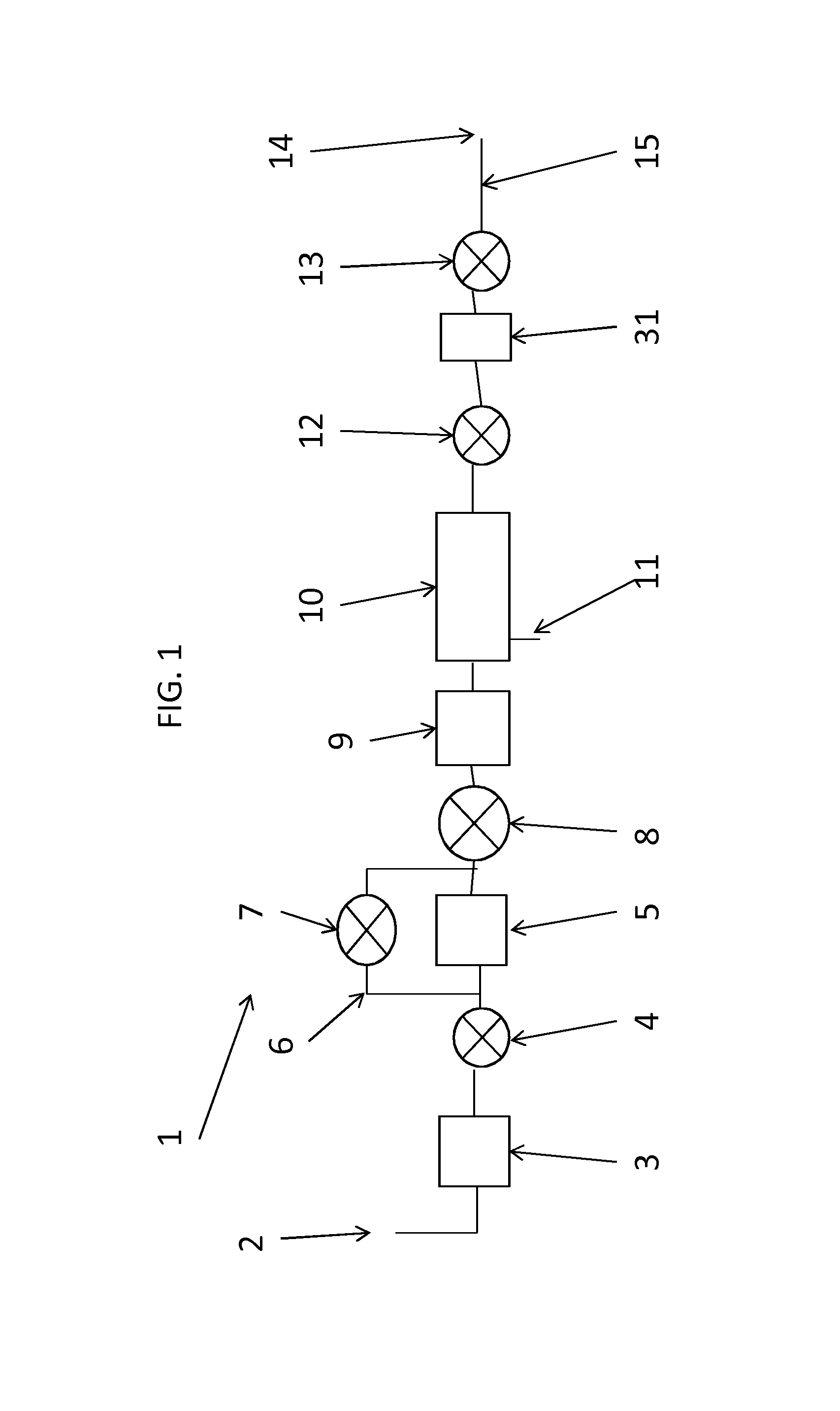
[0038]An embodiment of an aircraft fuel tank inerting arrangement of the present invention will now be described by reference to

[0039]FIG. 1. The aircraft fuel tank inerting arrangement is shown generally by reference numeral 1. The aircraft fuel tank inerting arrangement 1 comprises an inlet 2 arranged to receive air from an aircraft engine bleed line (not shown). The air received from the engine bleed line is typically at a temperature of about 350° C. The air passes downstream through an ozone remover 3 which removes ozone from the air. Ozone can cause problems to other components in the aircraft fuel tank inerting arrangement 1, in particular the air separation module 10 which is discussed in more detail below. Immediately downstream of the ozone remover 3 is a shut-off valve 4 which is closable to prevent gas moving upstream or downstream of the shut-off valve. The shut-off valve 4 is typically used as a safety valve. Downstream of the shut-off valve 4 is a heat exchanger 5 whi...


PUM


Abstract

A aircraft fuel tank inerting arrangement is provided for providing oxygen-depleted gas to one or more aircraft fuel tanks, the aircraft fuel tank inerting arrangement comprising a gas inlet, an oxygen remover configured to remove oxygen from an oxygen-containing gas, thereby producing an oxygen-depleted gas, a first flow control valve and at least one gas outlet to deliver oxygen-depleted gas to an aircraft fuel tank, the gas inlet being in gaseous communication with, and upstream of, the oxygen remover, the oxygen remover being in gaseous communication with, and upstream of, the at least one outlet, the first flow control valve being operable to provide a variable rate of flow of oxygen depleted gas to at least one gas outlet. An aircraft comprising such a aircraft fuel tank inerting arrangement is also provided, as is a method of providing oxygen-depleted gas to one or more aircraft fuel tanks

Description

FIELD OF THE INVENTION[0001]The present invention relates to aircraft fuel tank inerting arrangements, aircraft comprising such aircraft fuel tank inerting arrangements and methods of inerting aircraft fuel tank.BACKGROUND TO THE INVENTION[0002]It is known to provide an oxygen-depleted atmosphere to an aircraft fuel tank to reduce the risk of an explosion in the fuel tank. An air separation module removes some oxygen from the air, thereby providing oxygen-depleted air to one or more fuel tanks. The rate of oxygen-depleted air passed into a fuel tank typically depends on the stage of flight. For example, a low flow rate of oxygen-depleted gas may be used at the start of a flight (when a fuel tank may typically be full of fuel) and / or when a fuel tank is depressurising (e.g. on ascent). The flow rate of oxygen-depleted air is typically higher when there is less fuel in a fuel tank and / or a fuel tank is being re-pressurised (e.g. on a descent). A typical arrangement used to control flo...

Claims


Application Information

Patent Timeline
Patent Type & Authority Applications(United States)
IPC IPC(8): B64D37/32B64D37/34
CPCB64D37/34B64D37/32Y10T137/0318
Inventor HASKINS, RICHARDJONES, JOHN ALAN
Owner AIRBUS OPERATIONS LTD
Why Eureka
Try Eureka