
Rotary two-stroke internal combustion engine, particularly very high power very high speed engine fueled by solid particulate fuel like coal dust, destined for power generation

a technology of internal combustion engine and rotary two-stroke, which is applied in the direction of internal combustion piston engine, machine/engine, mechanical equipment, etc., can solve the problems of inability to meet the requirements of primemovers, inability to meet the overall efficiency of steam turbine power plants, and complicated technology and more expensive. , to achieve the effect of simple structure, high power density and simplified internal combustion engine technology

Inactive Publication Date: 2015-06-04
OLEDZKI WIESLAW JULIAN
View PDF12 Cites 0 Cited by
  • Summary
  • Abstract
  • Description
  • Claims
  • Application Information

AI Technical Summary

Benefits of technology

The present invention is a high power density positive-displacement internal combustion engine with the following technical effects: no reciprocating parts generating large mass forces, capable of revolving very fast, capable of developing large power, capable of withstanding extremely high loads, capable of working on highly efficient ultra-high pressure cycles without increasing specific loads of engine's elements beyond limits typical for ordinary piston engines, and without decreasing mechanical efficiency of the engine. Additionally, the invention provides a structure for a valve-less two stroke engine that guarantees good constraint for engine's piston and piston sealing elements.

Problems solved by technology

These engines, although now having been developed for more than century (almost 2 centuries in the case of Stirling), still stop short from fulfilling the requirements imposed on prime movers by modern economy.
Thus steam turbines require huge steam boilers and steam condensers and are troublesome to exploit, therefore their applications are restricted to power plants and propulsion of ships and some other heavy machinery.
Moreover the overall efficiency of steam turbine power plants is significantly inferior to that of large Diesel engines.
Gas turbines, thermal efficiency of which can achieve even 55% in large units destined for power generation and industrial applications (which in fact are compound heat machines with large heat exchanger), usually, particularly in small units, display much poorer figure than positive displacement engines, are more complicated technologically and more expensive, and therefore are unlikely to earn as dominant position as Diesels enjoy today due to these and other well-known inherent drawbacks and limitations.
Moreover, gas turbines require high quality, expensive fuels, and their ability to accept cheap solid particulate fuels (mainly pulverized coal) is problematic, due to unacceptably low durability of turbine's blades coming in contact with unburned hard solid particulates produced by burning pulverized coal.
However, Stirling engine is expensive to manufacture and troublesome to maintain, and this renders it considerably inferior to internal combustion engine in most applications, and prevents from earning wide acceptance.
Moreover, Stirling engine shares with diesels main disadvantages of reciprocating engines mentioned above.
However, so far none of those non-conventional engines, with Wankel-type engine being the only exception of economically (but certainly not conceptually) marginal importance, was successful, and probably none of them includes any chance to even go beyond the stage of prototyping.
Technically, this is due to the fact that the answer to the principal question any new engine is obliged to answer: “Does the new engine do its work better than conventional one?” is decidedly negative for all those non-conventional designs, including Wankel's.
(In the case of the Wankel engine, the answer to this more general question is positive, but superiority of Wankel over conventional engines in certain aspects (great power / weight and power / volume ratios, kinetic simplicity and smoothness of operation) is overshadowed by its inherent drawbacks (weak structure, inability to cope with large outputs, inferior efficiency, weakness of sealing, inherent inability to incorporate high compression ratios and to cope with large outputs)).
For example, recently patented positive displacement rotary engine, quasi-turbine, is complex both kinetically and structurally, its moving elements of complicated shapes are likely to be subjected to excessive thermal stresses and renders the engine weak structurally and more difficult to seal than Wankel engine; thus the engine is unlikely to do well the job of heat engine (it would be better as pump or compressor).
This not only makes these engines complex but also unreliable, as engine's elements that meet along a line are not well suited to bear shock loads met with in internal combustion engines.
Fuel cell is a very promising source of power for many applications, but it seems improbable it will become appropriate for applications where high power density and large power are essential in any foreseeable future.
Moreover maximum power achieved by reciprocating engines is approximately 80-87 MW (Wartsila-Sulzer RTA96-C or largest MAN-B&W 14-cylinder engines weighing ˜2300 metric tons), and largest reciprocating engines are not capable to revolve faster than approximately 100 rev / min due to large inertia mass forces generated by heavy reciprocating engine's parts (piston, piston rod, crosshead, and connecting rod, total weight of which amounts to tens of tons multiplied by the number of engine's cylinders), poor figures in comparison with steam turbines; all these drawbacks render reciprocating internal combustion engines impractical as far as large scale power generation is concerned.
Note, that increasing rotational speed of the RTA96 engine mentioned above to 3000 rev / min would increase its output to more than 2500 MW, a goal that obviously cannot be achieved due to at least 30-fold increase of mass forces that would inevitably have destroyed the engine (of course there are also other well known obstacles).
Moreover, none of the known positive-displacement internal combustion engines approaches highly desirable kinetic simplicity of gas turbines.

Method used


Image

  • Rotary two-stroke internal combustion engine, particularly very high power very high speed engine fueled by solid particulate fuel like coal dust, destined for power generation
  • Rotary two-stroke internal combustion engine, particularly very high power very high speed engine fueled by solid particulate fuel like coal dust, destined for power generation
  • Rotary two-stroke internal combustion engine, particularly very high power very high speed engine fueled by solid particulate fuel like coal dust, destined for power generation

Examples


Embodiment Construction

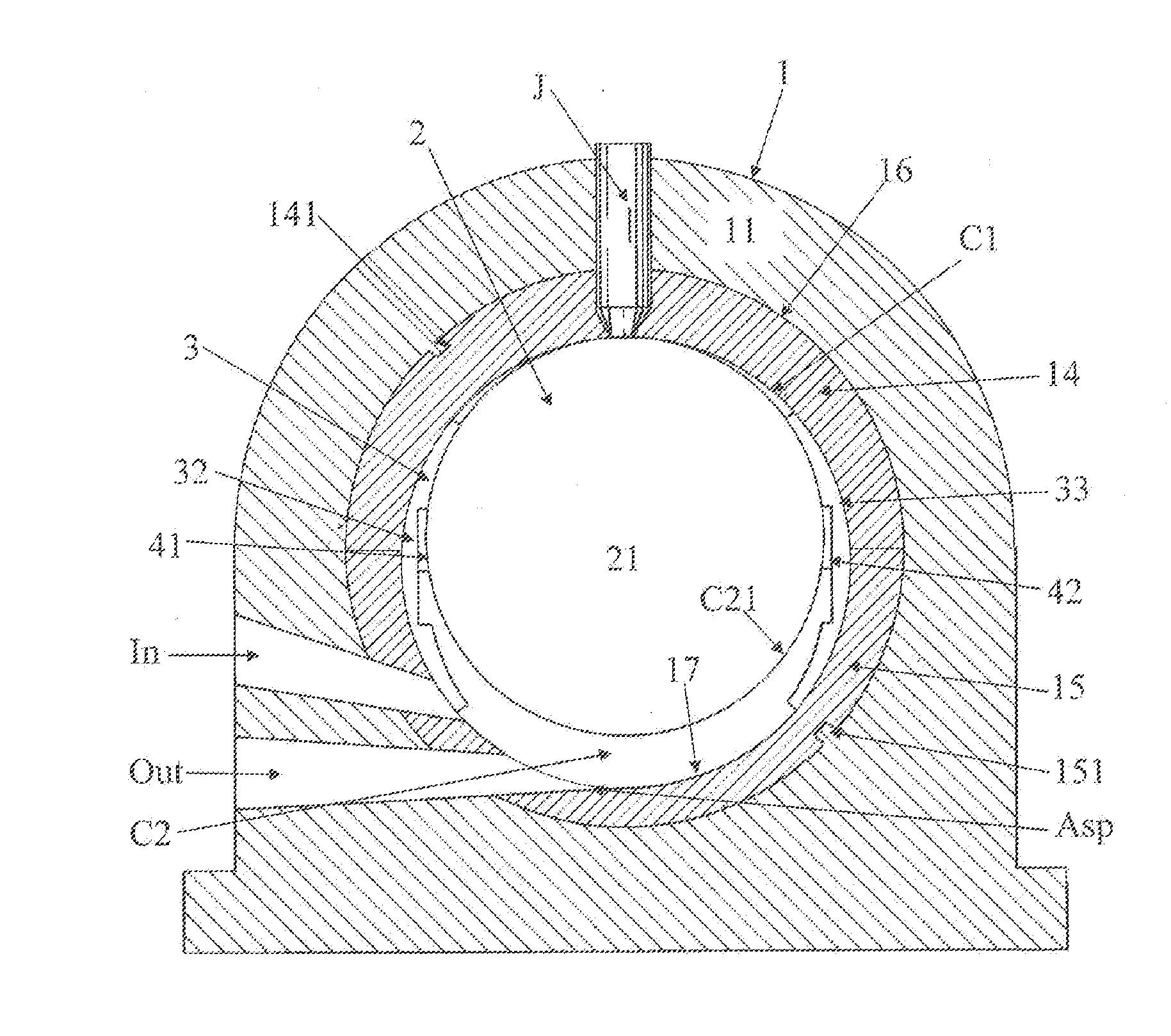
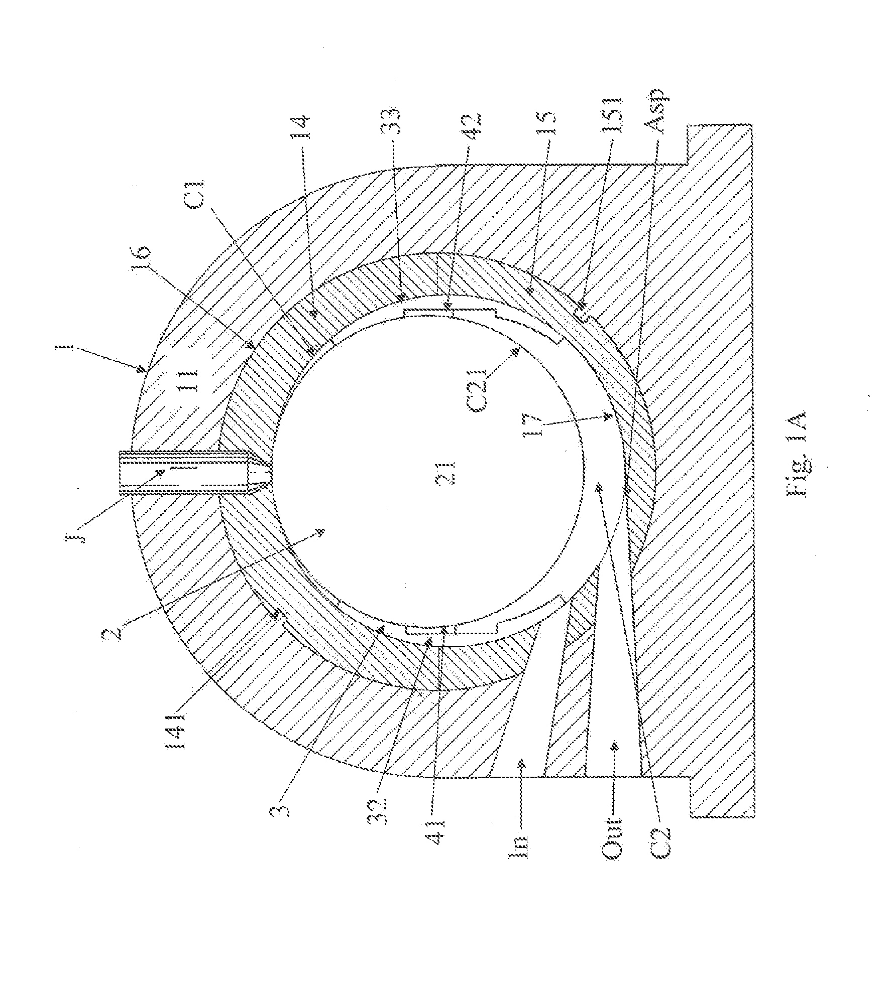
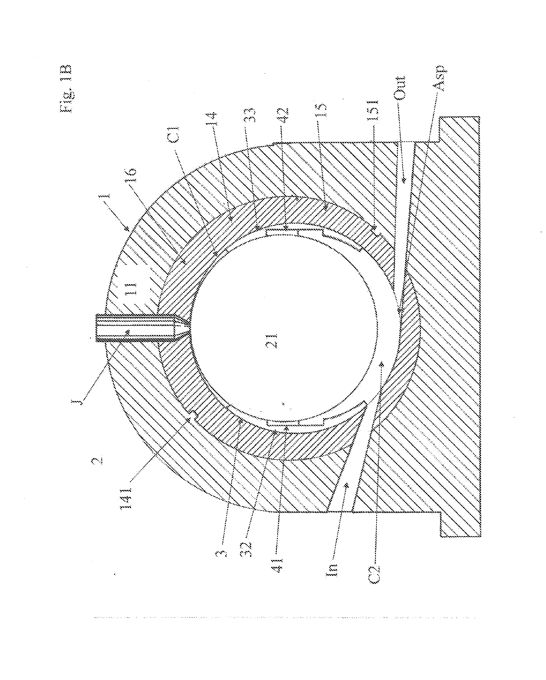
[0051]The engine being the first preferred embodiment of the invention (see FIGS. 1-8, 10, 22) consists of only two principal parts, namely a body 1 and an eccentric shaft 2 rotatably mounted in the body 1, wherein an eccentric of said eccentric shaft 2 is suitably sealed in the body 1 with the help of the primary sealing element 3 and secondary sealing elements 41, 42. The assembly of the body 1, the shaft 2, and the primary 3 and secondary sealing elements 41, 42 forms a 4-bar mechanism illustrated in FIG. 22, wherein the body 1, the shaft 2, the sealing element 3 and the sealing elements 41 and 42 correspond to elements 1, 2, 3, and 4 of said mechanism respectively (wherein the secondary sealing elements 41 and 42 move in unison and both correspond to the element 4 shown in the kinetic scheme in FIG. 22). Thus, from the kinetic point of view, the assembly of the body 1, the shaft 2, the primary sealing element 3, and the secondary sealing elements 41, 42, represents a four bar me...


PUM


Abstract

Rotary positive displacement internal combustion two stroke engine with only one major moving part, i.e. engine's eccentric shaft, with cylinders encompassing eccentrics of the shaft, with said eccentrics being suitably sealed in said cylinders, wherein combustion gases exert force directly on said eccentrics of said eccentric shaft. Gas forces can be nullified by suitably phasing shaft's eccentrics, thus nullifying gas forces loading shaft's bearings. The engine is naturally perfectly balanced. The engine possesses natural self-cleaning capability, and is capable of being fueled by coal dust. Units of the type developing 2 000 MW and 3 000-3 6000 rev / min, intended to replace steam turbines in power stations, can be built.

Description

TECHNICAL FIELD OF THE INVENTION[0001]The invention relates to heat engines and, more specifically, to positive displacement internal combustion engines, and is particularly concerned with very large rotary internal combustion engines fueled by solid particulate fuels like coal dust, destined to drive electric current generators, and intended to replace large steam turbines offering at least 50% overall efficiency in comparison with ˜40% overall efficiency of typical steam boiler-steam turbine assembly. Thus the invention solves the problem of building very large internal combustion positive displacement engines capable of revolving with very large rotational speeds (e.g. 3000-3600 rev. / min, like steam turbines) and developing very large outputs (2000 MW and more), as well as problems of fueling internal combustion engines by solid particulate fuels, and removing unburned solid residues from combustion chamber of internal combustion engine. The invention provides the optimal form fo...

Claims


Application Information

Patent Timeline
Patent Type & Authority Applications(United States)
IPC IPC(8): F02B53/02
CPCF02B53/02F02B25/26Y02T10/12
Inventor OLEDZKI, WIESLAW JULIAN
Owner OLEDZKI WIESLAW JULIAN
Learn More