Rotary projector light

a projector light and rotary technology, applied in the field of projector light, can solve the problems of limitation of conventional projector light, generated cloud lighting effect not meeting the lighting effect expected by users,

Active Publication Date: 2015-06-11
GEMMY IND CORP
View PDF5 Cites 57 Cited by
  • Summary
  • Abstract
  • Description
  • Claims
  • Application Information

AI Technical Summary

Benefits of technology

[0006]Embodiments of the present invention provide a rotary projector light to provide light of different colors projected at mult

Problems solved by technology

However, despite the foregoing dynamic cloud lighting effects, the conventional projector light has limitations when projecting light from different angles, onto a large area, and/or in a large occ

Method used


Image

  • Rotary projector light
  • Rotary projector light
  • Rotary projector light

Examples


Embodiment Construction

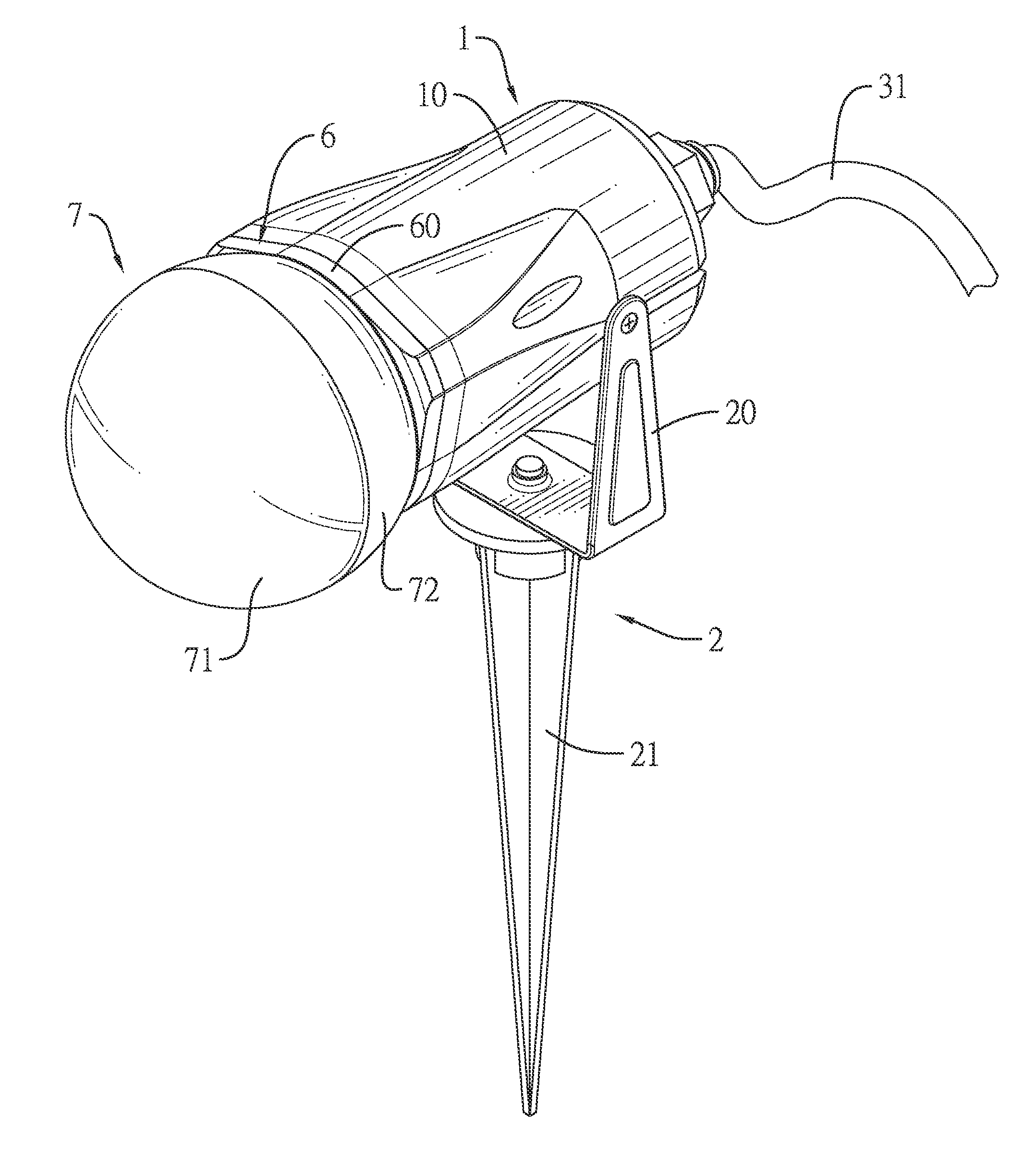
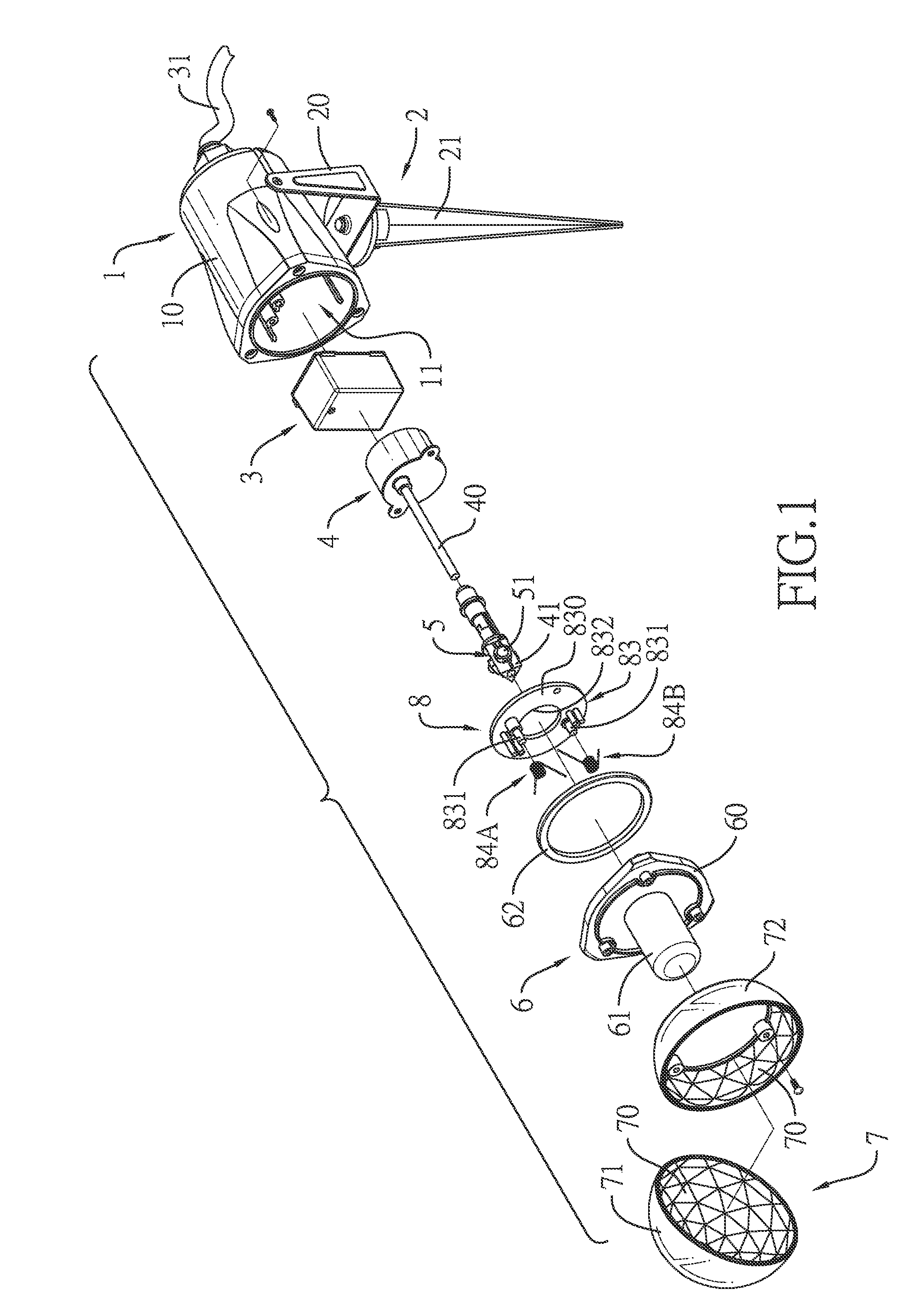
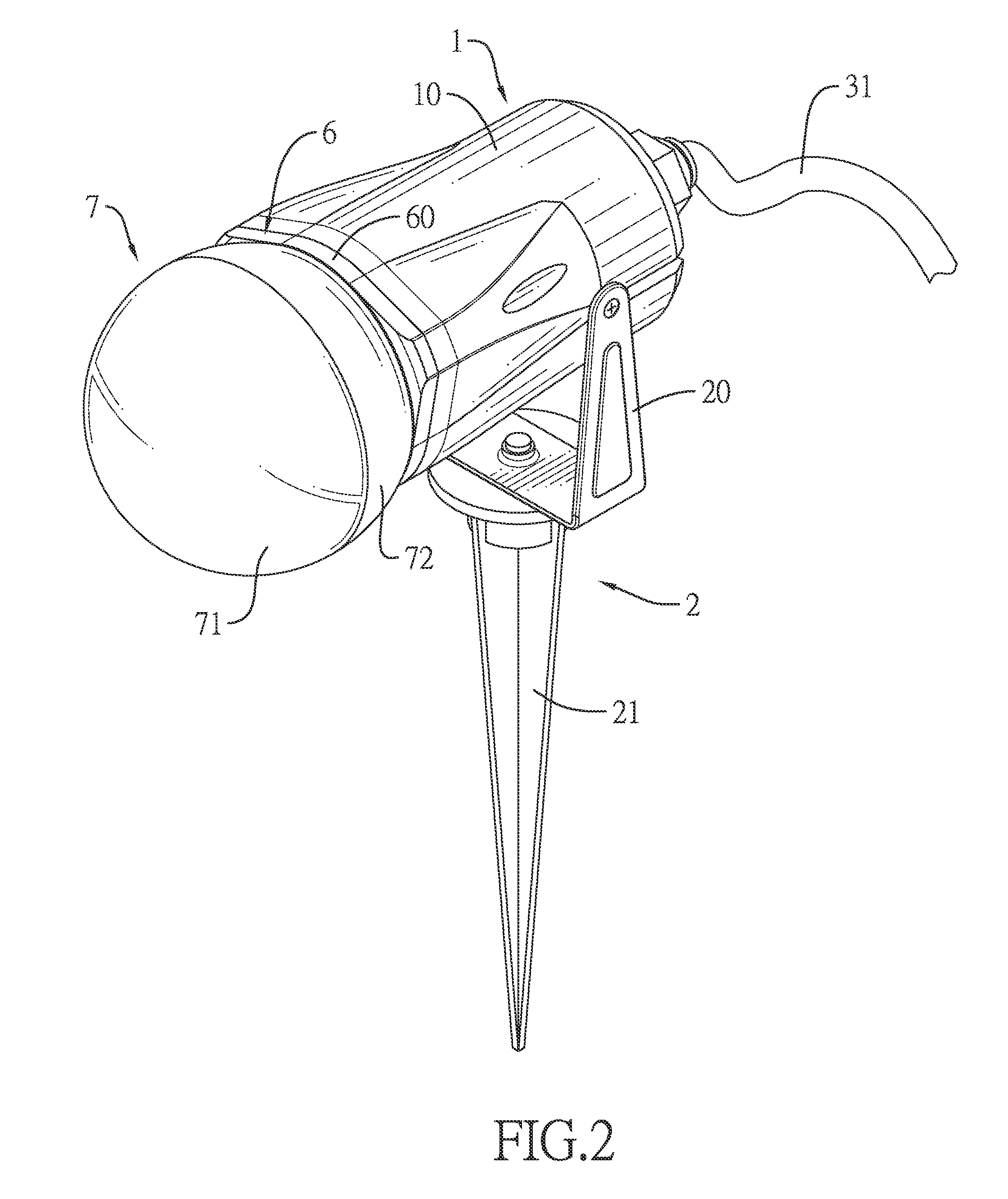
[0025]With reference to FIGS. 1 to 3, a rotary projector light in accordance with an embodiment of the present invention has a lamp case 1, a support stand 2, a power supply 3, a motor 4, a light-emitting diode (LED) device 5, a watertight lens assembly 6 and a beam-splitting lens cover 7.

[0026]The lamp case 1 is hollow with an open front end. In the present embodiment, the lamp case 1 has a peripheral wall 10, a mounting chamber 11 and a rear cover 12. The mounting chamber 11 is defined inside the lamp case 1 and surrounded by the peripheral wall 10, and the mounting chamber 11 communicates with the open front end. The rear cover 12 is mounted on a rear end of the peripheral wall 10 of the lamp case 1.

[0027]The support stand 2 is mounted on a bottom of the lamp case 1. In the present embodiment, the support stand 2 has a U-shaped bracket 20 and an insertion post 21. Two parallel bars of the U-shaped bracket 20 are mounted on two lateral portions of the peripheral wall 10 with a scr...


PUM


Abstract

A rotary projector light can include a lamp case defining a hollow mounting chamber and having an open front end; a power supply located inside the lamp case, the power supply connected to a power cable adapted to connect to an external power source; a motor located inside the lamp case, the motor electrically connected to the power supply and having a spindle; a positioning seat mounted on the spindle; a plurality of light emitting diode (LED) elements located on the positioning seat, the LED elements electrically connected to the power supply; and a beam-splitting lens cover located on the open front end of the lamp case. The beam-splitting lens cover can have an inner surface with multiple convex lenses directed at multiple refraction angles.

Description

BACKGROUND OF THE INVENTION[0001]1. Field of the Invention[0002]The present invention relates to a projector light, and more particularly, to a rotary projector light.[0003]2. Description of the Related Art[0004]Lighting plays a critical role on stage performance because of the creation of an animated and entertaining atmosphere. To provide diversified stage effect, stage equipment manufacturers have already designed a type of stage projector light that generates dynamic lighting effects. Such stage projector lights usually have a motor and a projector lamp. The projector lamp has a light source module and a light exit lens mounted inside a lamp enclosure. Given the variation of lights emitted by the light source module and refracted by the light exit lens, and the rotary and oscillating motion of the projector lamp driven by the motor, the projector lamp can create dynamic cloud lighting effects.[0005]However, despite the foregoing dynamic cloud lighting effects, the conventional p...

Claims


Application Information

Patent Timeline
IPC IPC(8): F21V21/30F21V5/04G02B27/12F21K99/00F21V31/00
CPCF21V21/30F21K9/58F21Y2101/02G02B27/123F21V5/04F21V31/00F21S10/06F21V21/0824F21W2131/406F21Y2113/13F21Y2115/10
Inventor ZHANG, CHENG-CHUN
Owner GEMMY IND CORP
Why Eureka
Try Eureka