Analyzing partial discharge in an electric power distribution system

Active Publication Date: 2015-06-11
TELEFON AB LM ERICSSON (PUBL)
View PDF8 Cites 19 Cited by
  • Summary
  • Abstract
  • Description
  • Claims
  • Application Information

AI Technical Summary

Benefits of technology

[0017]The present document also discloses a method in which a radio frequency or ultrasonic sensor is attached to a power cable. The sensor quantifies the magnitudes of partial discharge pulses. The pulses are measured during a power frequency cycle, and a separate count is made of those cycles having pulses whose measure exceeded a threshold and those that did not exceed a threshold. A percentage is calculated of the exceeding cycles out of a total number of cycles sensed.

Problems solved by technology

Therefore, the approaches described in this section may not be prior art to the claims in this application and are not admitted to be prior art by inclusion in this section.
In a power grid, buried medium voltage (MV) cables and high voltage (HV) cables degrade over time, especially early models that did not have a protective outer insulating cover and were buried directly in the ground.
However, this is an unintentional, undesirable, fallback.
The large number of cables, and economic limitations of utility companies, precludes a timely and systematic program of replacing the URD cables in most loc

Method used


Image

  • Analyzing partial discharge in an electric power distribution system
  • Analyzing partial discharge in an electric power distribution system
  • Analyzing partial discharge in an electric power distribution system

Examples


Example

[0026]A component or a feature that is common to more than one drawing is indicated with the same reference number in each of the drawings.

DESCRIPTION OF THE DISCLOSURE

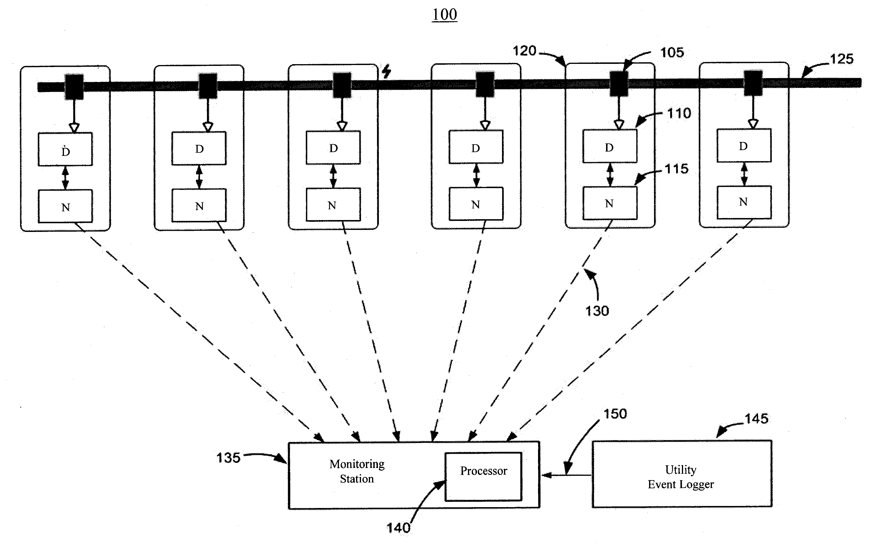
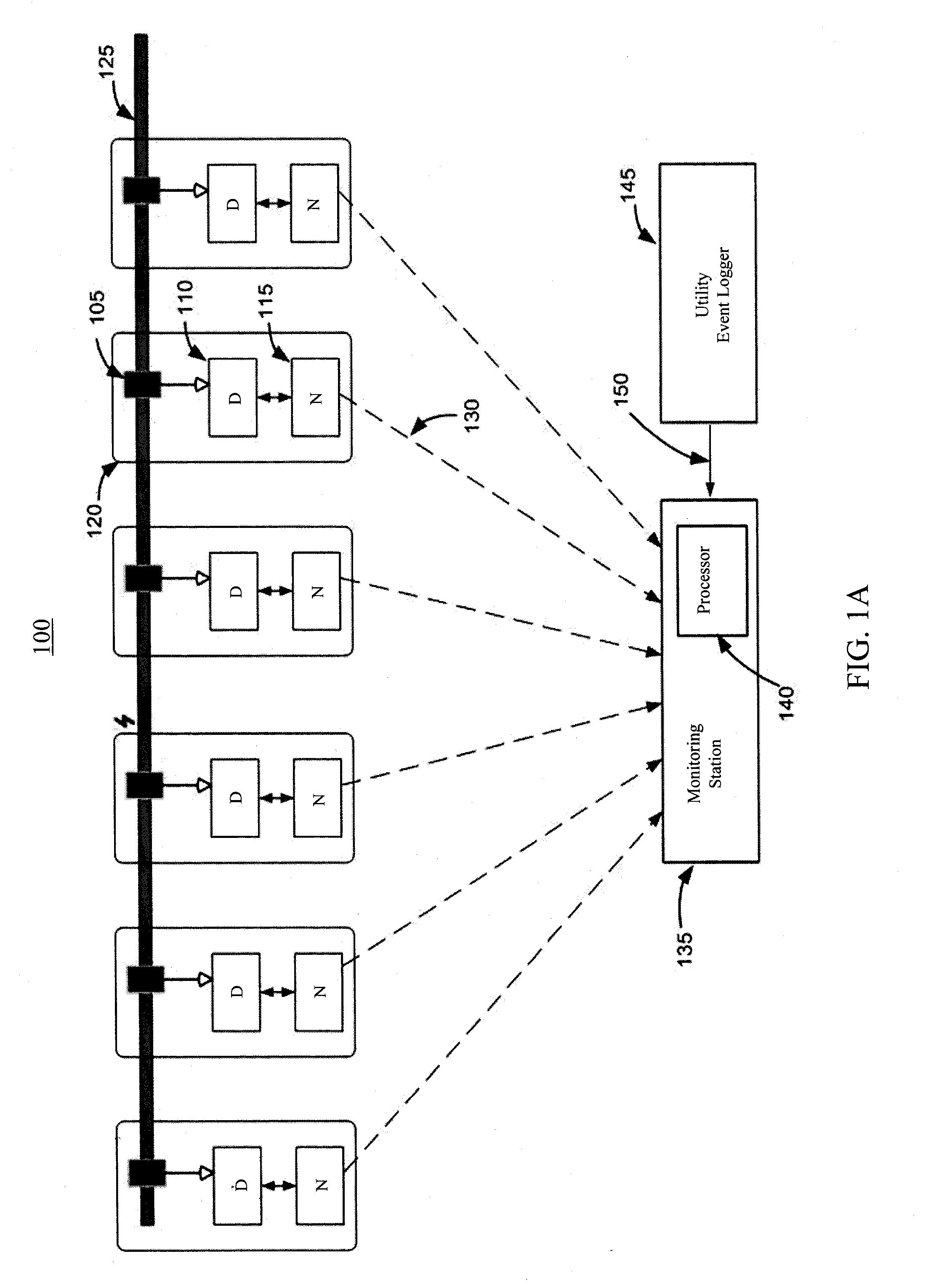
[0027]FIG. 1A is a block diagram of a system 100 for analyzing PD on a cable 125 in a power distribution system. System 100 includes a coupler 105, a detector 110, a node 115, a monitoring station 135, and a utility event logger 145.

[0028]Node 115 is in communication with monitoring station 135 by way of a link 130. Node 115 and detector 110 are related such that node 115 is a master and sends data requests to detector 110. Link 130 may be either a wire link or a wireless link. Monitoring station 135 includes a processor 140 that runs software termed a Network Management System (NMS).

[0029]Coupler 105 is an inductive coupler situated on cable 125 in a cabinet enclosing connections to transformer 120. Cable 125 is a URD cable and transformer 120 is a distribution transformer. If PD or arcing is present on a cable 125 a...


PUM


Abstract

There is provided a method that includes (a) detecting a partial discharge on a power line that carries a power signal, (b) measuring a characteristic of the partial discharge, thus yielding a measured characteristic, (c) determining that the measured characteristic satisfies a measurement criterion, thus yielding a qualified partial discharge, (d) incrementing a count of cycles of the power signal that contain qualified partial discharges, (e) calculating, for a plurality of cycles of the power signal, based on the count, a percentage of the plurality of cycles that contain qualified partial discharges, and (f) utilizing the percentage in a subsequent operation. There is also provided a system that performs the method, and a storage device that contains instructions for a processor to perform the method.

Description

BACKGROUND OF THE DISCLOSURE[0001]1. Field of the Disclosure[0002]The present disclosure relates to power lines for distribution of electrical power, and more particularly, to an evaluation of noise and excess current on the power lines, for the sake of identifying a location of a source of the noise or excess current.[0003]2. Description of the Related Art[0004]The approaches described in this section are approaches that could be pursued, but not necessarily approaches that have been previously conceived or pursued. Therefore, the approaches described in this section may not be prior art to the claims in this application and are not admitted to be prior art by inclusion in this section.[0005]In a power grid, buried medium voltage (MV) cables and high voltage (HV) cables degrade over time, especially early models that did not have a protective outer insulating cover and were buried directly in the ground. Such cables often have a coaxial cross-section. An exposed outer neutral sheat...

Claims


Application Information

Patent Timeline
IPC IPC(8): G01R31/12
CPCG01R31/1272G01R31/12
Inventor CERN, YEHUDA
Owner TELEFON AB LM ERICSSON (PUBL)
Why Eureka
Try Eureka