Low-water cut-off system

Inactive Publication Date: 2004-07-01
NAT CITY BANK CO
View PDF26 Cites 17 Cited by
  • Summary
  • Abstract
  • Description
  • Claims
  • Application Information

AI Technical Summary

Benefits of technology

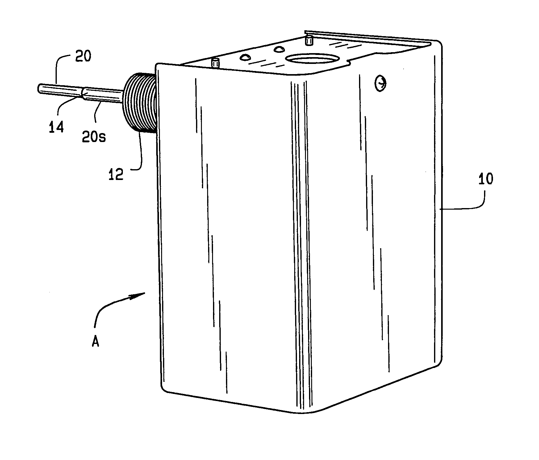
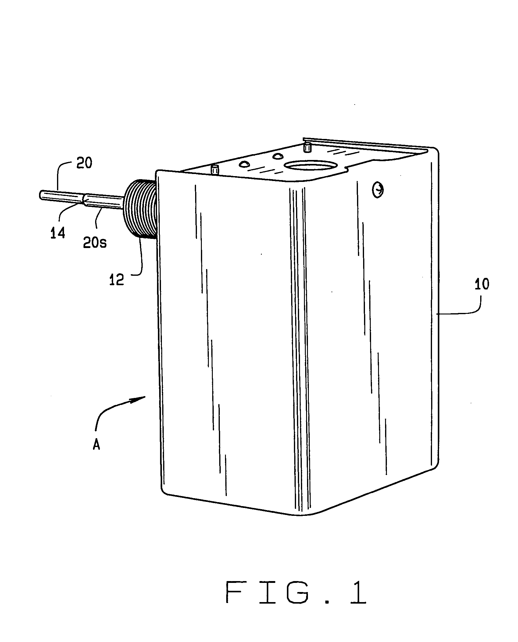
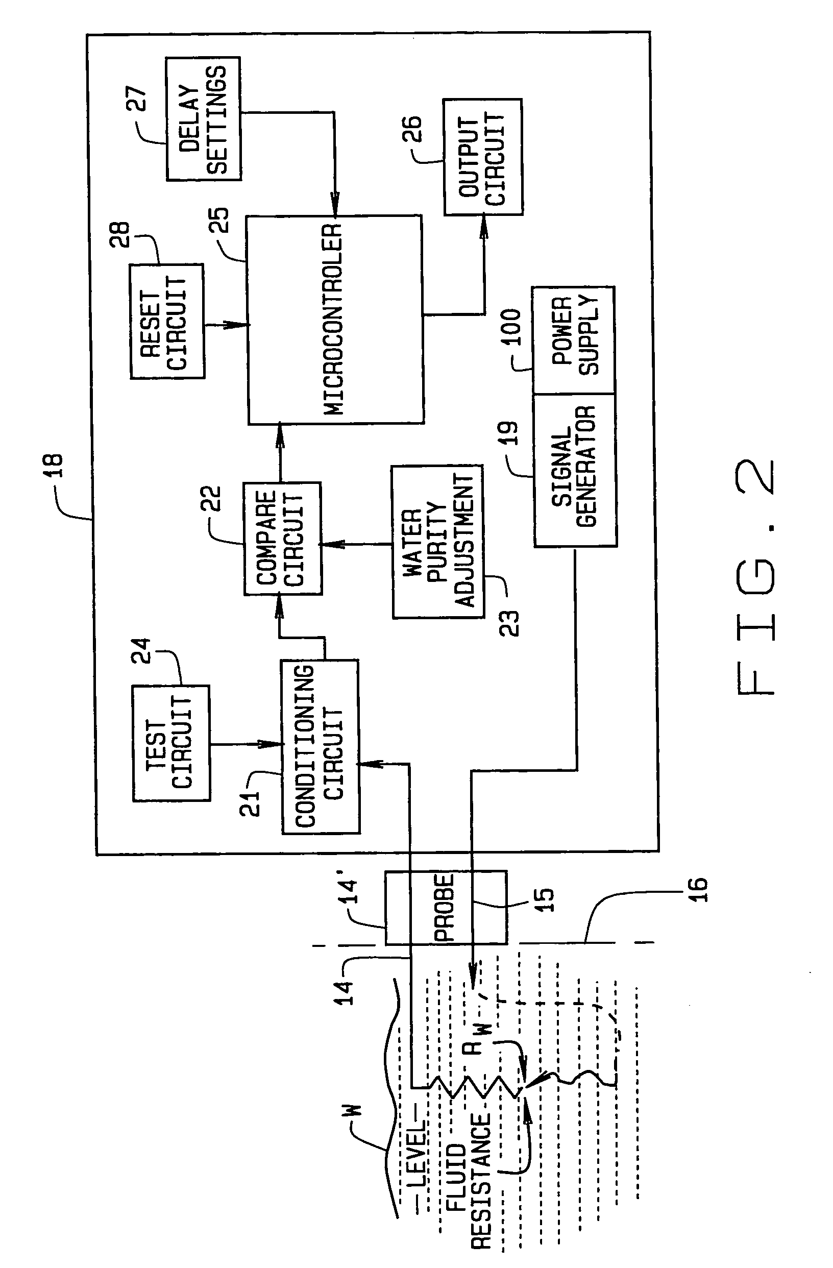
0047] More specifically summarized, the low water cut-off system of the present invention is a microprocessor-based control system for detecting the presence of an electrically conductive fluid in a vessel or tank, such as a boiler. It includes a probe for signaling a low water condition in the boiler or other vessel or tank. The system is provided with an adjustable time delay feature for preventing rapid shuttling of the device between on and off conditions whenever the water level is fluctuating about the probe. It also includes a water purity feature that permits the user to change the conductance level of the probe in order to increase detection sensitivity when accounting for higher levels of water purity in the boiler in accordance with the electrical conductivity of the fluid. The system includes a housing containing electronic circuitry and the probe, which is operatively connected to the electronic circuitry and extends outwardly from a brass bushin

Problems solved by technology

For example, fluid level in a boiler may fluctuate during operation, causing a possibility of possibly spurious, inaccurate or premature operation.
Because low water cut-off systems of the type operating according to electrical conductivity of water or other liquid require the fluid to be conductive in order to sense its presence, high purity water, which exhibits very low electrical conductivity, can fool the device into a false low water condition.
Accordingly, it is preferred that a low water cut-off system using a probe be responsive to electrical conductivity and be capable of adjustment in probe sensitivity; however the prior art has not provided a satisfactory low water cut-off system with suitable probe and electronics arrangement in which the system is responsive to electrical conductivity.
A difficulty in achieving such performance is that the designer is confronted, on the one hand, with a need for scaling, or attenuating, the input signal provided by a signal passing through water to be monitored at a current level which is dependent upon the conductance of the water; but also, on the oth

Method used


Image

  • Low-water cut-off system
  • Low-water cut-off system
  • Low-water cut-off system

Examples


Example

[0080] Referring now to FIG. 4, a second embodiment B of a low-water cut-off system circuitry 18 is now replaced by circuitry or system electronics including two networks supplied by a power supply 110 and an output circuit 126. The networks, as designated 122A and 122B, provide separate signal paths. Each such network has conditioning circuits, as explained below, with circuit elements similar to those of FIG. 3, and operational amplifier comparators having similarity to those of FIG. 3, as network 122A has comparators U1A and U1D, while network 122B has comparators U1B and U1C.

[0081] Network 122A is provided to receive positive-going pulses picked up by probe 14' input 14, but network 122B is provided to receive negative-going pulses. In this regard, recognize that transformer T10 is used to provide an alternating current signal which injected into the water to be monitored by the low-water cut-off system.

[0082] An input for network 122A is provided across a regulator diode SS1 ac...


PUM


Abstract

A low-water cut-off system [A] determines if fluid [W] within a boiler or other enclosure drops below a predetermined level within the enclosure. A signal generator introduces a signal into the enclosure so that the signal is present for sensing at the predetermined level, where a probe is provided for sensing the signal if present as occurs if the water is at the predetermined level. A control, which includes a microcontroller, is responsive to the probe for providing a control function in response to whether the signal is so sensed by the probe, and so to determine if water has dropped below the predetermined level. The function may be causing alarm signalling or boiler heating cut-off. Self-test and time delay features are also included. Provision is made so that the control compensates for variation in electrical conductivity of the water through which the probe signal is sent, including circuitry to adjust for a wide range of possible purity levels. Provision is included such that the low water cut-off system is fault tolerant no matter at what water purity it is adjusted to operate.

Description

[0001] This application is a continuation-in-part of pending application Ser. No. 10 / 154,730, filed May 24, 2002, which claims priority from U.S. Provisional Patent Application Serial No. 60 / 293,444, filed May 24, 2001.[0002] 1. Field of the Invention[0003] The present invention relates to fluid level detection systems and, more particularly, to an advantageous low-water cut-off system that operates in any of a wide range of conditions and provides precise level detection with an extraordinarily wide variety of electrically conductive fluids.[0004] Although the term low water cut-off system is herein used, it will be understood as being applicable to systems using fluids other than water which exhibit electrical conductivity that can be sensed for the present purposes. The term low water cut-off system is used in its general sense, regardless of the fluid to be sensed.[0005] 2. Known Art.[0006] Low water cut-off systems have long been used in low-pressure and hot water boilers to cu...

Claims


Application Information

Patent Timeline
IPC IPC(8): G01F23/24
CPCG01F23/243
Inventor MERWIN, JEFFREY
Owner NAT CITY BANK CO
Why Eureka
Try Eureka