Mass spectrometer and mass spectrometric method

Inactive Publication Date: 2005-05-03
HITACHI HIGH-TECH CORP
View PDF17 Cites 17 Cited by
  • Summary
  • Abstract
  • Description
  • Claims
  • Application Information

AI Technical Summary

Benefits of technology

[0023]In the mass spectrometer of the present invention, the gas pressure in the ion trap can be switched at high speed, and the respective switched pressures can be held almost constant. Specifically, a bath gas (such as Ar or N2) having a heavy mass is intermittently introduced in a collisional activated dissociation process of precursor ions having a mass to be detected to conduct CID (collision

Problems solved by technology

Problems remain in the respective methods.
It is difficult to set a supplemental voltage condition at the collisional activated dissociation dependent largely on the gas pressure to an optimum.
This significantly reduces the ion utilization efficiency (duty cycle) of the entire apparatus to largely lower the sensitivity.
This, however, signifi

Method used


Image

  • Mass spectrometer and mass spectrometric method
  • Mass spectrometer and mass spectrometric method
  • Mass spectrometer and mass spectrometric method

Examples


Example

(Embodiment 1)

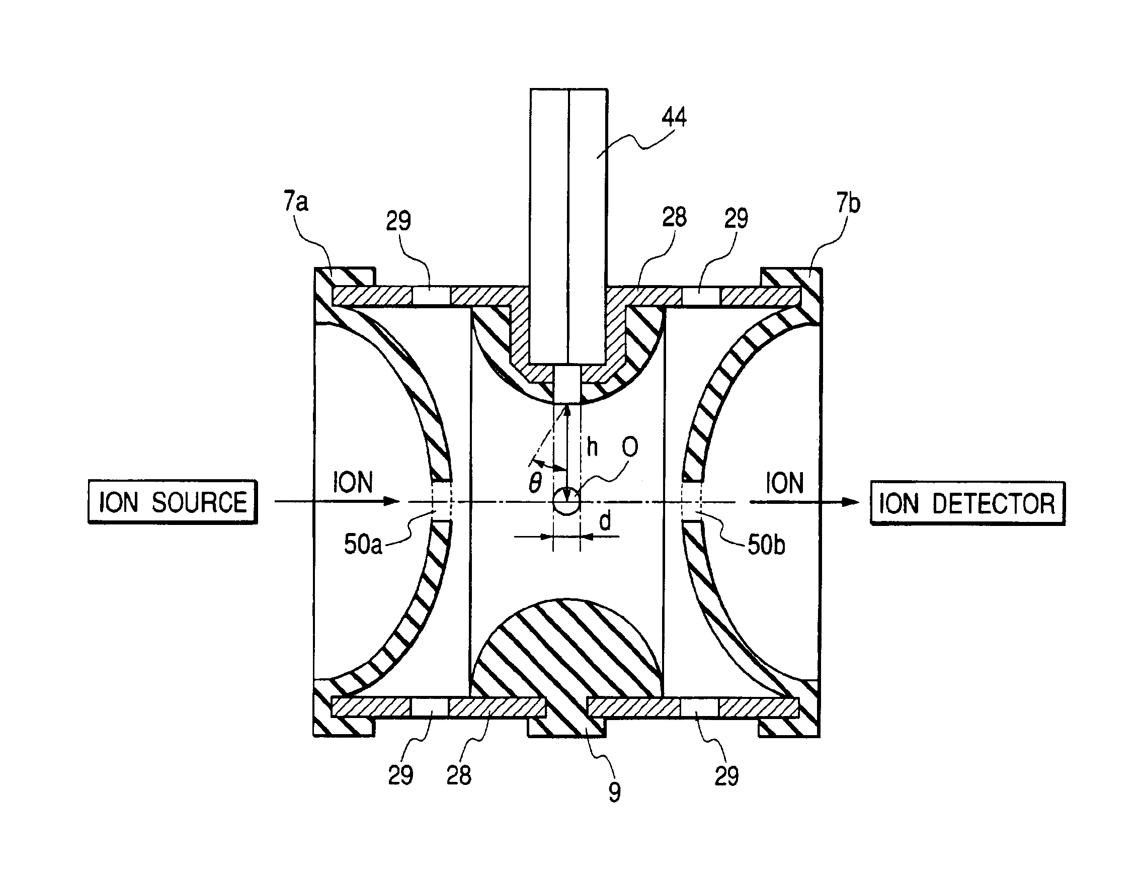
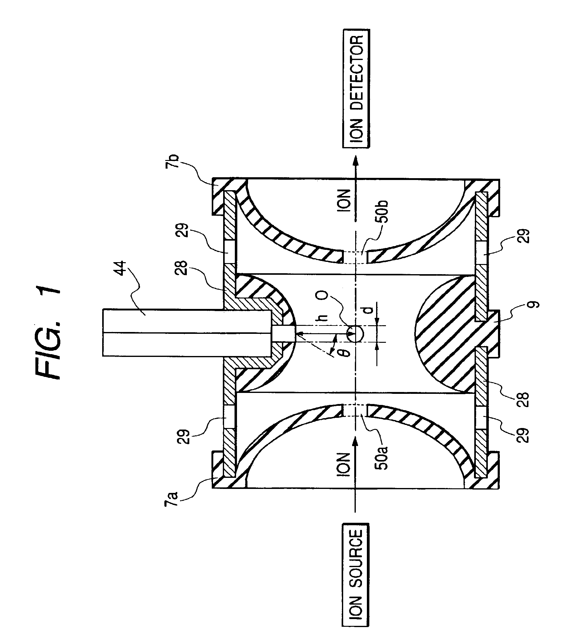
[0042]An embodiment of a quadruple ion trap of the present invention will be described with reference to FIG. 1.

[0043]FIG. 1 is across-sectional view of the embodiment of the quadruple ion trap of the present invention. The quadruple ion trap constructs a cylindrical ion trap region whose both-side end surfaces are recessed in a bowl shape by a pair of opposed endcap electrodes 7a, 7b in a bowl shape, a donut-like ring electrode 9, and cylindrical insulators 28 for coupling the ring electrode 9 and the endcap electrodes 7a, 7b and electrically insulating the ring electrode 9 and the endcap electrodes 7a, 7b. The endcap electrode 7a is formed with a hole (ion incidence hole) 50a into which ions are incident. The endcap electrode 7b is formed with a hole (ion ejection hole) 50b from which ions are ejected. A suitable number of small apertures 29 are distributively provided on the insulators 28. The ring electrode 9 is provided with a hole having inner diameter d. A pulse...

Example

[0069]FIG. 4 is a second embodiment of the present invention and is a cross-sectional view of main construction parts of a construction example of an atmospheric pressure ionization ion trap mass spectrometer using the ion trap of Embodiment 1 using an electrospray ion source. Embodiment 2 shown in FIG. 4 can be applied to all kinds of atmospheric pressure ion sources in the same manner.

[0070]The atmospheric pressure ionization ion trap mass spectrometer of Embodiment 2 has an atmospheric pressure ion source 100, a first differentially pumping region 200 at a vacuum level introducing sample ions generated by the ion source 100 via an orifice 3, a second differentially pumping region 300 at a vacuum level communicated via an orifice 4 with the first differentially pumping region 200 guiding ions by octapoles 5a, 5b, and a third differentially pumping region 400 at a vacuum level communicated via an orifice 14 with the second differentially pumping region 300 guiding ions by octapoles...

Example

(Embodiment 3)

[0105]FIG. 12 is Embodiment 3 of the present invention and is a diagram showing a construction example of a mass spectrometer having a construction which applies ion dissociation by laser irradiation to the atmospheric pressure ionization ion trap mass spectrometer explained in Embodiment 2. Parts similar to those of FIG. 4 are indicated by the same reference numerals. As is apparent from comparison of both, in the mass spectrometer of Embodiment 3, the process in which ions generated by the ion source 100 are introduced into the ion trap 500 and the process in which fragment ions are detected are the same as those of the mass spectrometer of Embodiment 2. This embodiment is different from Embodiment 2 in that a window 15 is provided in the position opposite the orifice 14 of the third differentially pumping region 400 and a laser beam is incident therefrom. The incident laser beam is irradiated through the hole 50b on the endcap electrode 7b onto the region O near the...


PUM


Abstract

There is provided an ion trap mass spectrometer which can detect fragment ions having a low mass and enables high-sensitivity measurement. A mass spectrometer has an ion source generating sample ions; an ion trap having a pair of and endcap electrodes and a ring electrode and accumulating ions generated by the ion source and isolating precursor ions from the accumulated ion and dissociating the isolated precursor ions and ejecting the dissociated ions from the ion trap. A gas introduction hole is arranged in the endcap electrode or the ring electrode for introducing in intermittently-introduced bath gas therethrough into the ion trap. A detector detects the ions ejected from the ion trap. The center axis of the gas introduction hole is arranged so as to pass through a region near the center of gravity of the ion trap.

Description

FIELD OF THE INVENTION[0001]The present invention relates to all mass spectrometers which can apply a quadruple ion trap, such as a quadruple ion trap mass spectrometer, a quadruple ion trap-time-of-flight mass spectrometer, and a quadruple ion trap-Fourier transformed ion cyclotron resonance mass spectrometer.BACKGROUND OF THE INVENTION[0002]As an example of various mass spectrometric methods, there is an ion trap mass spectrometric method. The basic principle of a quadruple ion trap mass spectrometric method is known (Patent Document 1). In the ion trap method, an RF voltage having a frequency of about 1 MHz is applied to a ring electrode to accumulate ions. In an ion trap, ions having above a certain mass become in a stable condition to be accumulated. The lower voltage applied to the ring electrode is swept to the higher one. In this case, the ions having a low mass are first ejected to obtain a mass spectrum.[0003]In this method, however, different kinds of ions having the same...

Claims


Application Information

Patent Timeline
IPC IPC(8): H01J49/34H01J49/42G01N27/62
CPCH01J49/0481H01J49/424
Inventor HASHIMOTO, YUICHIROHASEGAWA, HIDEKIBABA, TAKASHIWAKI, IZUMI
Owner HITACHI HIGH-TECH CORP
Why Eureka
Try Eureka