Rotating electric machine

a rotating electric machine and electric motor technology, applied in the direction of dynamo-electric machines, magnetic circuit rotating parts, magnetic circuit shape/form/construction, etc., can solve the problems of difficult to obtain the effect of reducing the torque pulsation at a skew angle to be derived theoretically, and the torque reduction of the rotating electric machine becomes significant, so as to suppress the magnetic flux leakage, the effect of reducing the torque pulsation and suppressing the torqu

Active Publication Date: 2015-06-11
MITSUBISHI ELECTRIC CORP
View PDF4 Cites 14 Cited by
  • Summary
  • Abstract
  • Description
  • Claims
  • Application Information

AI Technical Summary

Benefits of technology

[0009]According to the rotating electric machine of one embodiment of the present invention, the non-magnetic portions of the adjacent blocks overlap with each other in the axial direction, and the non-magnetic portions of each of the blocks are formed on the circumferentially outer side of the permanent magnet. Therefore, it is possible to suppress a situation where the magnetic flux generated in the radially-outer side surface of the permanent magnet of one of the adjacent blocks flows in the axial direction from the circumferentially outer side of the permanent magnet to enter the radially-inner side surface of the permanent magnet of the other of the adjacent blocks. Thus, the magnetic flux leakage can be suppressed, with the result that the torque pulsation can be reduced and the torque reduction can be suppressed.

Problems solved by technology

Thus, it becomes difficult to obtain an effect of reducing the torque pulsation at a skew angle to be derived theoretically.
Further, the magnetic flux passing through the stator core is reduced, thus leading to a problem in that the torque reduction of the rotating electric machine becomes significant.

Method used


Image

  • Rotating electric machine
  • Rotating electric machine
  • Rotating electric machine

Examples


first embodiment

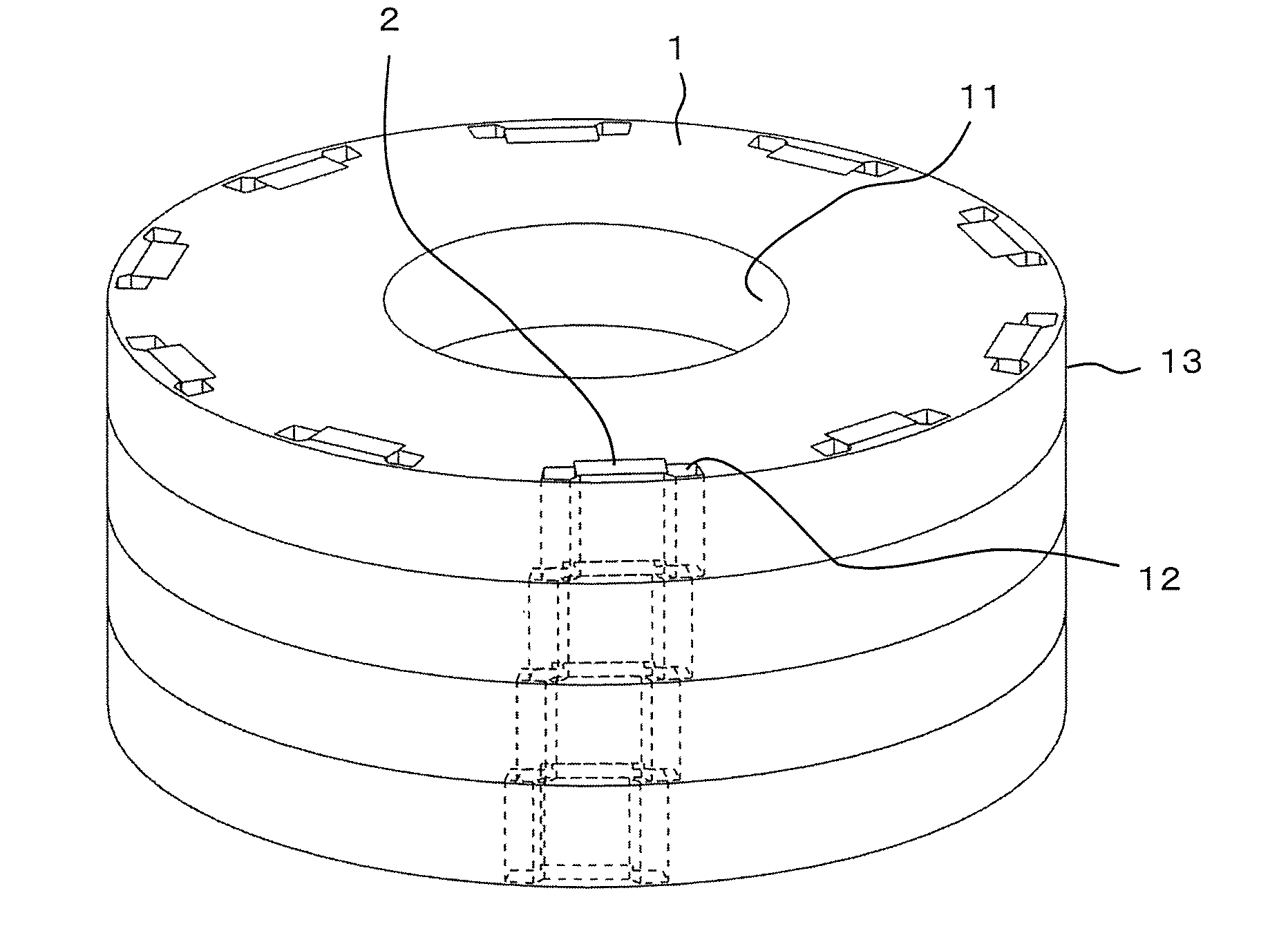
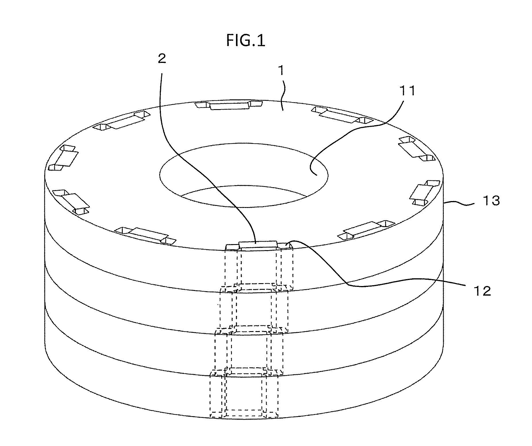
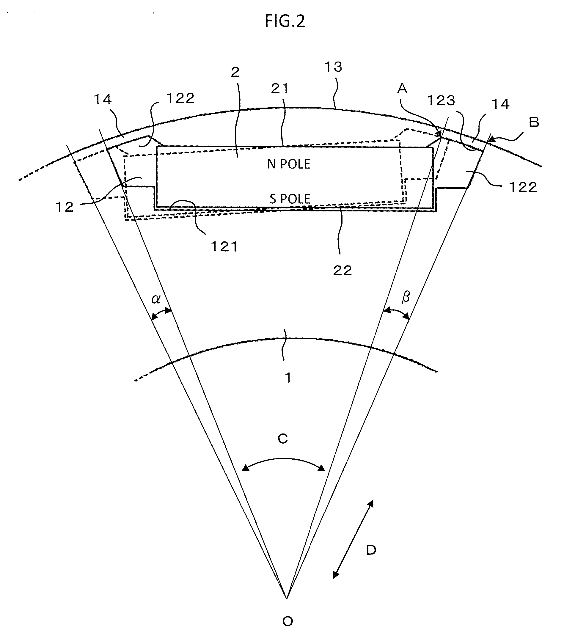
[0020]FIG. 1 is a perspective view illustrating a rotor according to a first embodiment of the present invention. FIG. 2 is a main-part enlarged view illustrating the rotor of FIG. 1 as seen in an axial direction thereof. In FIGS. 1 and 2, the rotor includes a rotation shaft (not shown), a rotor core 1 formed into an annular shape and rotatable about the rotation shaft, and a plurality of permanent magnets 2 embedded in the rotor core 1.

[0021]A rotation shaft through hole 11 into which the rotation shaft is inserted is formed on a radially inner side of the rotor core 1.

[0022]The rotor core 1 is divided into a plurality of blocks in the axial direction. In this example, the rotor core 1 is divided into four-stage blocks in the axial direction. Further, the blocks of the rotor core 1 are arranged to have a predetermined phase angle therebetween in a circumferential direction of the rotor core 1 so that a stepped skew is formed in the rotor core 1. Each of the blocks is constructed by...

second embodiment

[0034]FIG. 3 is a perspective view illustrating a rotating electric machine according to a second embodiment of the present invention. FIG. 4 is a main-part enlarged view illustrating the rotating electric machine of FIG. 3 as seen in an axial direction thereof. In FIGS. 3 and 4, the rotating electric machine includes a rotor 3, and a stator 4 arranged on a radially outer side of the rotor 3.

[0035]In the rotor 3, a pair of permanent magnets 2 arranged into a substantially V-shape in plan view is inserted into a pair of magnet through holes 12, to thereby form one magnetic pole. A desired number of the magnetic poles are formed by the pair of permanent magnets 2 in the circumferential direction of the rotor core 1. Each of the permanent magnets 2 that form two adjacent magnetic poles is inserted into the magnet through hole 12 so that the N pole and the S pole are inverted. Other components of the rotor 3 are similar to those of the rotor of the first embodiment.

[0036]Coils of the st...

third embodiment

[0047]FIG. 5 is a main-part plan view illustrating a rotating electric machine as seen in an axial direction thereof according to a third embodiment of the present invention. In FIG. 5, in each of the plurality of blocks divided in the axial direction, a circumferential width Wb of the bridge portion 14 is equal to or larger than the circumferential width Wt at the distal end of the tooth 411 of the stator core 41 (Wb≧Wt).

[0048]The circumferential width Wb of the bridge portion 14 refers to a distance between the magnetic pole center-side end A of the bridge portion 14 and the magnetic pole outer-side end B of the bridge portion 14. Other components are similar to those of the second embodiment.

[0049]As described above, according to the rotating electric machine of the third embodiment of the present invention, it is possible to suppress a situation where a magnetic flux generated at the N magnetic pole of each of the blocks sneaks from the circumferential end of the N magnetic pole...


PUM


Abstract

A rotating electric machine includes a rotor including: a rotor core divided into blocks in an axial direction, the blocks being arranged to have a phase angle therebetween in a circumferential direction, the rotor core having magnet through holes arrayed in the circumferential direction and formed in an outer circumferential region; and permanent magnets inserted into the magnet through holes. The magnet through hole includes: a magnet insertion portion into which the permanent magnet is inserted; and a non-magnetic portion provided on an outer side of the magnet insertion portion in the circumferential direction. A bridge portion is formed between the outer circumferential surface and an outer circumferential inner wall of the non-magnetic portion. A bridge angle, which is an angle between both circumferential ends of the bridge portion with a rotation center of the rotor core set as a vertex, is larger than a skew angle.

Description

BACKGROUND OF THE INVENTION[0001]1. Field of the Invention[0002]The present invention relates to a rotating electric machine including a rotor divided into a plurality of blocks in an axial direction of the rotor, which are arranged to be offset in a circumferential direction of the rotor.[0003]2. Description of the Related Art[0004]In a synchronous motor including an interior permanent magnet rotor having permanent magnets embedded in an outer circumferential region of a rotor core, the distribution of a magnetic field generated between a stator and the rotor is not an ideal sine wave distribution in a gap between the stator and the rotor, and magnetic saturation occurs in the rotor core due to the magnetic field. For those reasons, when the rotor is rotated, the magnetic flux distribution density in the gap between the stator and the rotor does not exhibit a smooth profile, and hence torque pulsation such as cogging torque and torque ripples occurs in the rotor. This torque pulsat...

Claims


Application Information

Patent Timeline
Patent Type & Authority Applications(United States)
IPC IPC(8): H02K1/27H02K3/18
CPCH02K1/276H02K2201/06H02K3/18H02K1/2766H02K2213/03
Inventor ISODA, HITOSHIINOUE, MASAYANISHIMURA, SHINJIHAZEYAMA, MORIYUKITACHIBANA, TOMOYA
Owner MITSUBISHI ELECTRIC CORP
Why Eureka
Try Eureka