Control device of rotary electric machine and control method of the same

Active Publication Date: 2021-12-28
HITACHI ASTEMO LTD
View PDF8 Cites 0 Cited by
  • Summary
  • Abstract
  • Description
  • Claims
  • Application Information

AI Technical Summary

Benefits of technology

[0017]With a drive control device of the rotary electric machine according to the invention and a drive device of the rotary electric machine equipped with the drive control device, the torque pulsation can be

Problems solved by technology

Then, the permanent magnet dynamo-electric machine may genera

Method used


Image

  • Control device of rotary electric machine and control method of the same
  • Control device of rotary electric machine and control method of the same
  • Control device of rotary electric machine and control method of the same

Examples


Embodiment Construction

[0027]Hereinafter, embodiments of the invention will be described using the drawings.

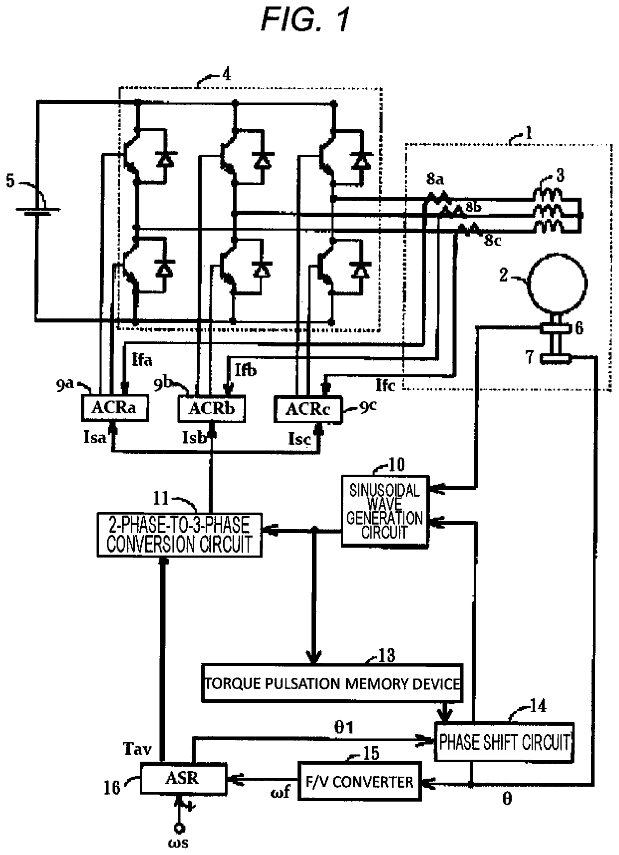
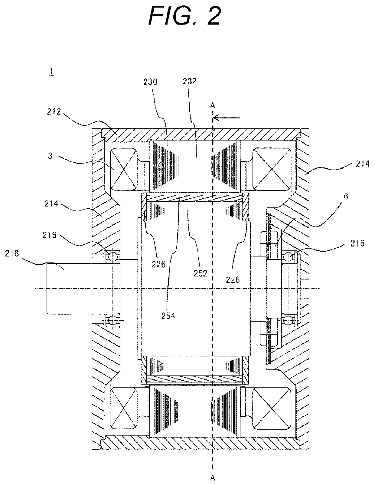
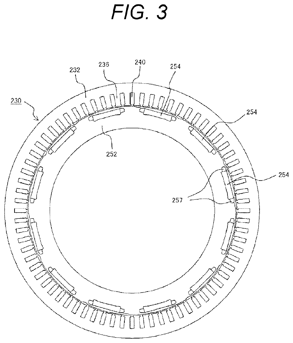
[0028]FIG. 1 is a circuit block diagram of a control device of a permanent magnet dynamo-electric machine 1 in this embodiment. FIG. 2 is a cross-sectional view taken along an axial direction of the permanent magnet dynamo-electric machine 1 of this embodiment. FIG. 3 is a cross-sectional view of the permanent magnet dynamo-electric machine 1 when viewed from a direction of arrow of a cross section AA of FIG. 2.

[0029]In FIGS. 1 to 3, reference numeral 1 denotes a permanent magnet dynamo-electric machine, reference numeral 2 denotes a rotor, and reference numeral 3 denotes a stator winding. The rotor 2 includes a rotor core 252 fitted to a shaft 218, and a permanent magnet 254 provided in a stator core 252. In the shaft 218, a position detector 6 to detect a magnetic pole position of the rotor 2 and an encoder 7 to detect a rotation speed are attached.

[0030]On the other hand, the stator 230 includes ...


PUM


Abstract

An object of the invention is to reduce a torque pulsation. A control device of a rotary electric machine according to the invention includes a sinusoidal wave generation circuit which generates a sinusoidal wave signal according to a magnetic pole position of a rotor of the rotary electric machine, a current command circuit which generates a speed command, a torque command based on actual speed information, and a current command on the basis of the sinusoidal wave signal, and a current control circuit which controls an inverter circuit interposed between a stator winding and a DC power source to make a sinusoidal current flow to the stator winding on the basis of the current command and a current detection signal of the stator winding of the rotary electric machine, wherein the current control circuit periodically changes a current phase of the sinusoidal current when the rotary electric machine is driven by a predetermined torque and a predetermined rotation frequency.

Description

TECHNICAL FIELD[0001]The present invention relates to a control device of a rotary electric machine, and particularly to a reduction in pulsation of a magnetic flux caused from a winding slot and in torque pulsation caused from cogging torque.BACKGROUND ART[0002]A permanent magnet dynamo-electric machine includes a stator and a rotor. The stator includes a stator core where winding slots disposed at almost equal intervals and a stator winding provided in the winding slots. A magnetomotive force distribution of the stator winding becomes a distribution where spatial harmonics are superimposed on a sinusoidal wave (fundamental wave) and varies with time in proportion to the winding current of the stator. In addition, since an opening and a teeth portion of the winding slot are disposed at almost equal intervals in the stator core, the distribution of a magnetic permeance of the stator core also contains ripples of the period of the winding slot. Therefore, a magnetic flux density form...

Claims


Application Information

Patent Timeline
IPC IPC(8): H02K1/14H02P6/10H02P6/15H02K1/16H02K3/12H02P27/06
CPCH02P6/10H02K1/16H02K3/12H02P6/15H02P27/06H02K11/21H02K21/14H02P6/17
Inventor MATSUNOBU, YUTAKAHOSHINO, KATSUHIRO
Owner HITACHI ASTEMO LTD
Why Eureka
Try Eureka