Brushless DC Electric Motor

Inactive Publication Date: 2010-08-12
BUGLAEV OLEG ANATOLIEVICH
View PDF9 Cites 0 Cited by
  • Summary
  • Abstract
  • Description
  • Claims
  • Application Information

AI Technical Summary

Benefits of technology

[0011]It is an object of this invention to provide a solution for increasing the stability and reliability of operation of the brushless DC electric motor, and for reducing the torque pulsations of the electric motor.
[0014]The novel features of the present invention provide the device with new properties, which are very important for the practical application of said device. Electric connection between the inverter and the control unit is prevented due to the fact that the control unit comprises option transmitters, and the inverter comprises optron receivers, the optical inputs of said receivers being optically coupled to the outputs of said option transmitters thus forming an optron pair with said option transmitters. Therefore, fluctuations of the supply voltage, defects of the power source or the inverter itself cannot damage the control unit; furthermore, high power currents of the electromechanical converter winding cannot influence the control unit through the inverter, which significantly increases stability of the electric motor operation and virtually prevents the occurrence of emergency operating mode; therefore, it becomes possible to significantly increase the capacity of the electric motor, in particular, towards values required for application of the motor in electric drives of dental equipment mechanisms.
[0015]Finally, the existence of the electric motor start-up unit makes it possible to exclude from the process the integrating circuits, which inevitably possess different inherent parameters and cause additional torque pulsations in the prototype; reduction of said pulsations significantly improves the operational qualities of the electric motor.

Problems solved by technology

The disadvantage of said brushless DC electric motor consists in that there is a shift at the outputs of the integrating circuits relative to the common terminal when the motor operates in the mode of rotation frequency stabilization, which results in different switching thresholds of the rotational-EMF comparators and, consequently, in different lead angles at which the sections are powered during positive and negative intervals of the rotational EMF.
Nonsymmetric voltage shapes at the armature winding sections result in additional torque pulsations, increased detonation and, consequently, deterioration of operating qualities of the brushless DC electric motor.
It should also be mentioned that high power currents of the electromechanical converter winding have a negative effect on the control unit through the inverter, which leads to unstable operation of the electric motor (emergency operation mode).
The abovementioned disadvantages become even more pronounced upon increase of required capacity of the brushless DC electric motor, which narrows the list of possible applications of the prototype device, limiting it to low-load electric drives, for example, drives of magnetic tape-driving mechanisms of tape recorders.
Another serious disadvantage of the prototype consists in the fact that special integrating circuits are used for starting the electric motor.
The inevitable dispersion of parameters of said circuits produces a certain shift at their outputs relative to the common terminal in the mode of rotation frequency stabilization, which creates additional torque pulsations of the electric motor.
The prototype device does not provide a satisfactory solution for reducing said pulsations (due to the abovementioned dispersion of parameters of the integrating circuits), although pulsations in RU 2091978 C1 are somewhat smaller than in SU 1774455 A1.

Method used


Image

  • Brushless DC Electric Motor
  • Brushless DC Electric Motor
  • Brushless DC Electric Motor

Examples


Embodiment Construction

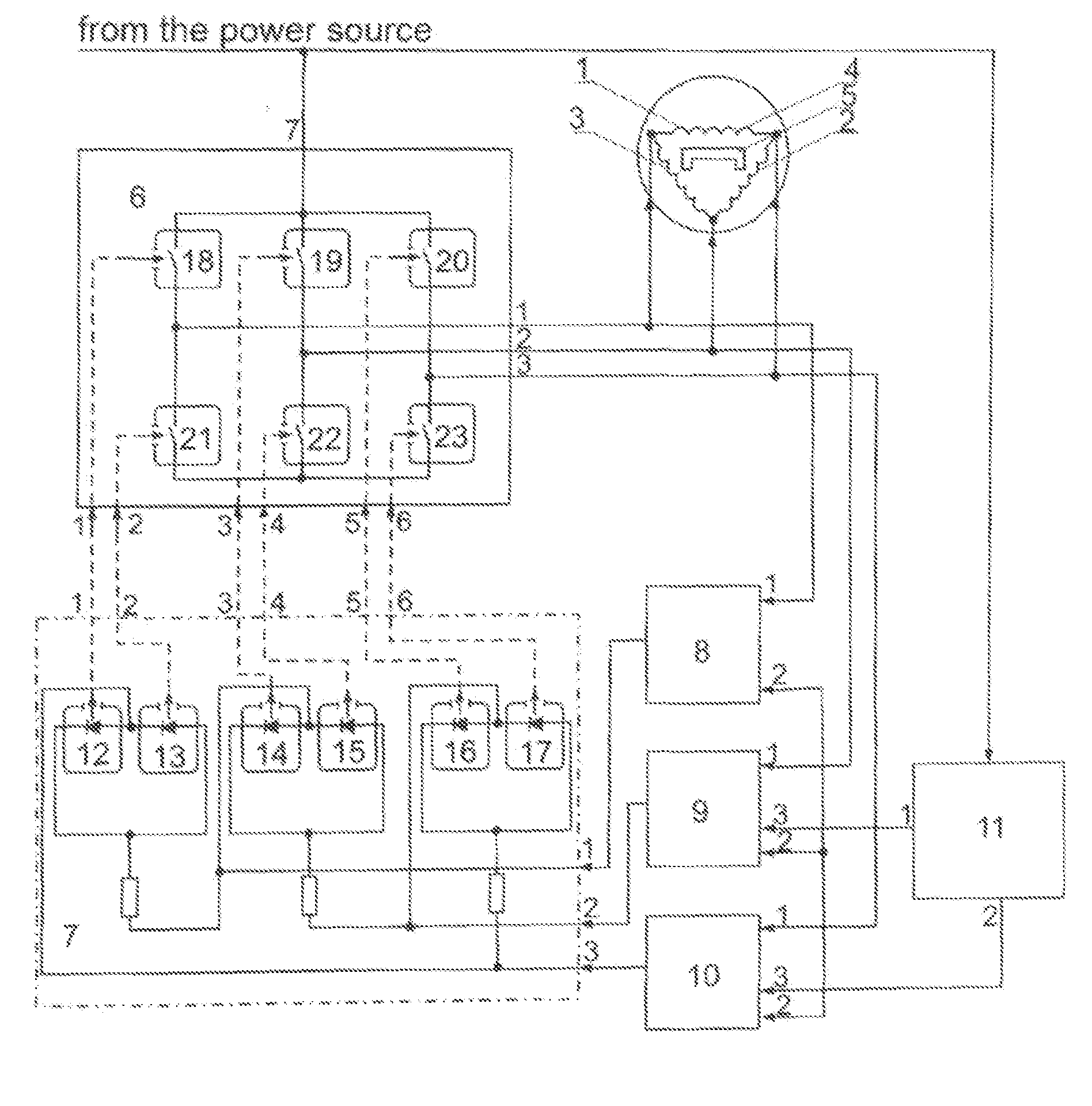
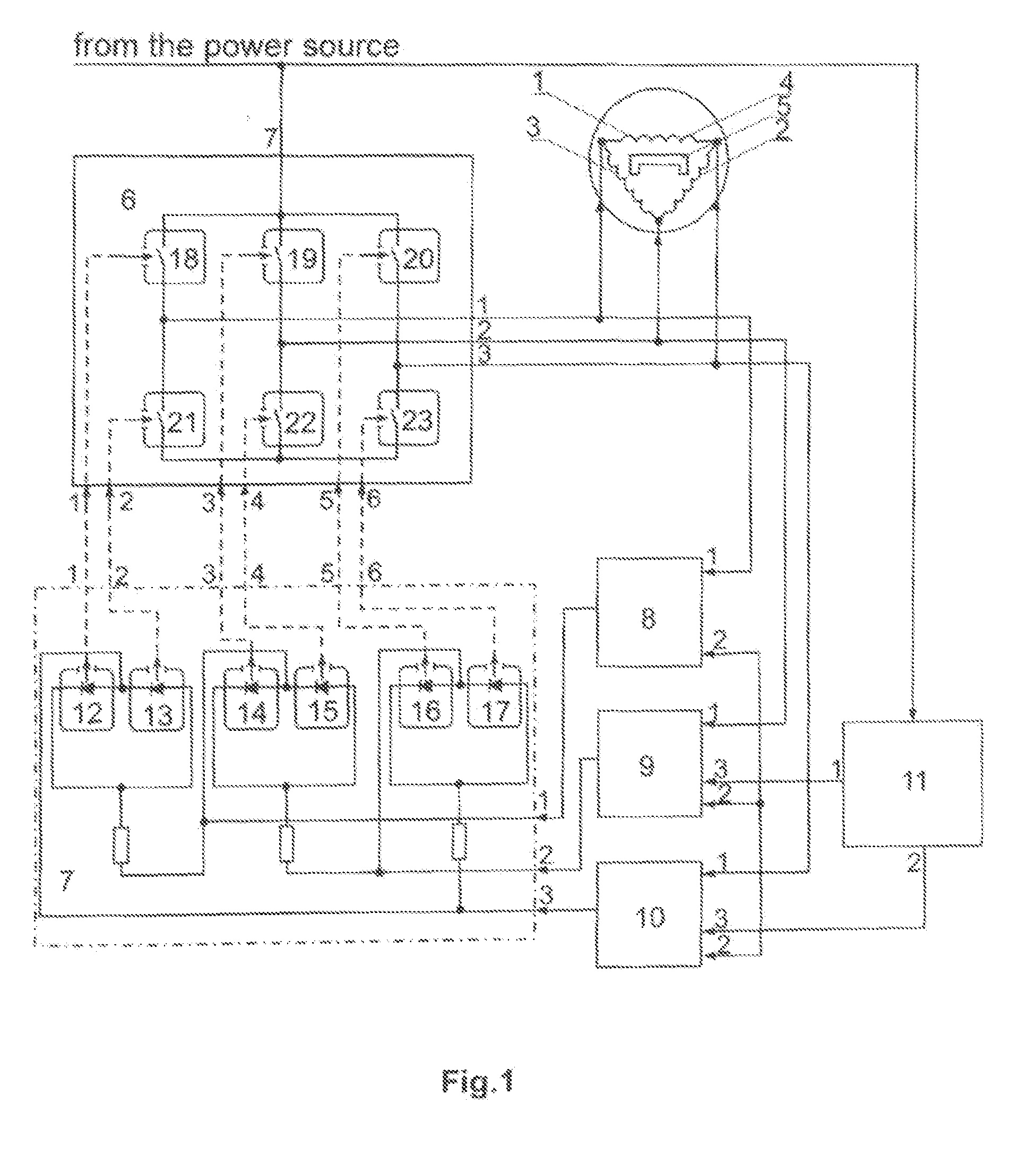
[0020]The brushless DC electric motor is connected to a power source, in particular, to a controlled switching regulator (not shown in the figure), and comprises an electromechanical converter 1 with a three-section winding (sections 2, 3 and 4), in this particular embodiment the sections are interconnected in a triangle-like circuit; however, they can also be interconnected in a star-like circuit. Inductor 5 is based on permanent magnets. The inventive device also comprises an inverter 6, a control unit 7, 1st comparator 8, 2nd comparator 9 and 3rd comparator 10; the terminals of sections of the electromechanical converter winding are connected to the 1st, 2nd and 3rd outputs of the inverter 6, respectively, as well as with the 1st inputs of the 1st comparator 8, 2nd comparator 9 and 3rd comparator 10, respectively; the inventive device also comprises an electric motor start-up unit 11. Said control unit 7 comprises six optron transmitters 12, 13, 14, 15, 16 and 17 with optical out...


PUM


Abstract

The invention relates to electrical engineering and can be used, in particular, in electric drives of mechanisms used in dental equipment. A brushless DC electric motor comprises an electromechanical converter (1) with a three-section (2, 3, 4) winding and a permanent-magnet inductor (5), an inverter (6), a control unit (7) and three comparators (1st (8), 2nd (9) and 3rd (10)), wherein the terminals of the winding sections of said electromechanical converter are connected to the 1st, 2nd and 3rd outputs of the inverter (6), respectively, and to the 1st inputs of the 1st (8), 2nd (9) and 3rd (10) comparators, respectively, said motor additionally comprising an electric motor start-up unit (11); and wherein said control unit (7) is a decoder and comprises six optron transmitters (12, 13, 14, 15, 16 and 17) with optical outputs, while the inverter comprises six optron receivers (18, 19, 20, 21, 22 and 23), the optical inputs of said receivers being connected by means of optical coupling to corresponding optical outputs of said optron transmitters (12, 13, 14, 15, 16 and 17) of the control unit (7), and wherein the outputs of the 1st (8), the 2nd (9) and the 3rd (10) comparators are connected to the 1st, 2nd and 3rd inputs of the control unit (7), respectively, while the 7th power input of the inverter (6) is connected to the power source and to the input of the electric motor start-up unit (11), the 1st output of said start-up unit (11) being connected to the 3rd input of the 2nd (9) comparator, its 2nd output being connected to the 3rd input of the 3rd (10) comparator, and wherein the 2nd inputs of all comparators are interconnected with each other. The present invention provides an increase of operational reliability and stability of the brushless DC electric motor, as well as reduction of the torque pulsations.

Description

TECHNICAL FIELD[0001]The invention relates to electrical engineering and can be used, in particular, in electric drives of mechanisms used in dental equipment.BACKGROUND ART[0002]A known controlled brushless DC electric motor comprises an electromechanical converter with a permanent-magnet inductor, the 1st terminals of the three sections of the armature winding of said inductor being joined together and connected to the common bus of the brushless DC electric motor, a full-wave frequency converter, the outputs of said converter being connected to the 2nd terminals of the armature winding sections, a logical control unit, the outputs of said control unit being connected to the control inputs of the full-wave frequency converter, and three comparators, each having two inputs, the outputs of said comparators being respectively connected to the inputs of the logical control unit. The brushless DC electric motor also comprises three integrating circuits. The 1st input of the i-th compar...

Claims


Application Information

Patent Timeline
IPC IPC(8): H02P6/14
CPCH02P6/20H02P6/182
Inventor BUGLAEV, OLEG ANATOLIEVICHBRYZGALOV, VIKTOR ALEXEVICH
Owner BUGLAEV OLEG ANATOLIEVICH
Why Eureka
Try Eureka