This helps you quickly interpret patents by identifying the three key elements:
Problems solved by technology
Method used
Benefits of technology
Benefits of technology
The present patent aims to provide a circuit breaker control module that can protect against accidents caused by arcing when there is a failure in a power system or distribution line. The module uses an electronic semiconductor switching structure to first break the failure line, reducing the risk of accident. Additionally, the patent aims to increase the stability and reliability of the control circuit by insulating it from the failure line through which failure current flows.
Problems solved by technology
As the number of cut-off times increases, the cut-off switches may be damaged.
Thus, when the surge voltage, overvoltage, overcurrent, etc. occurs on the power transmission and distribution line, the controller or the meter was electrically affected.
Thus, when the controller or the meter is directly affected by the overvoltage / overcurrent, stability and reliability thereof have to be remarkably deteriorated.
Thus, the circuit breaker and the circuit breaker controller are exposed to electrical hazards.
Method used
Image
Click on the blue label to locate the original text in one second.
Reading with bidirectional positioning of images and text.
Examples
first embodiment
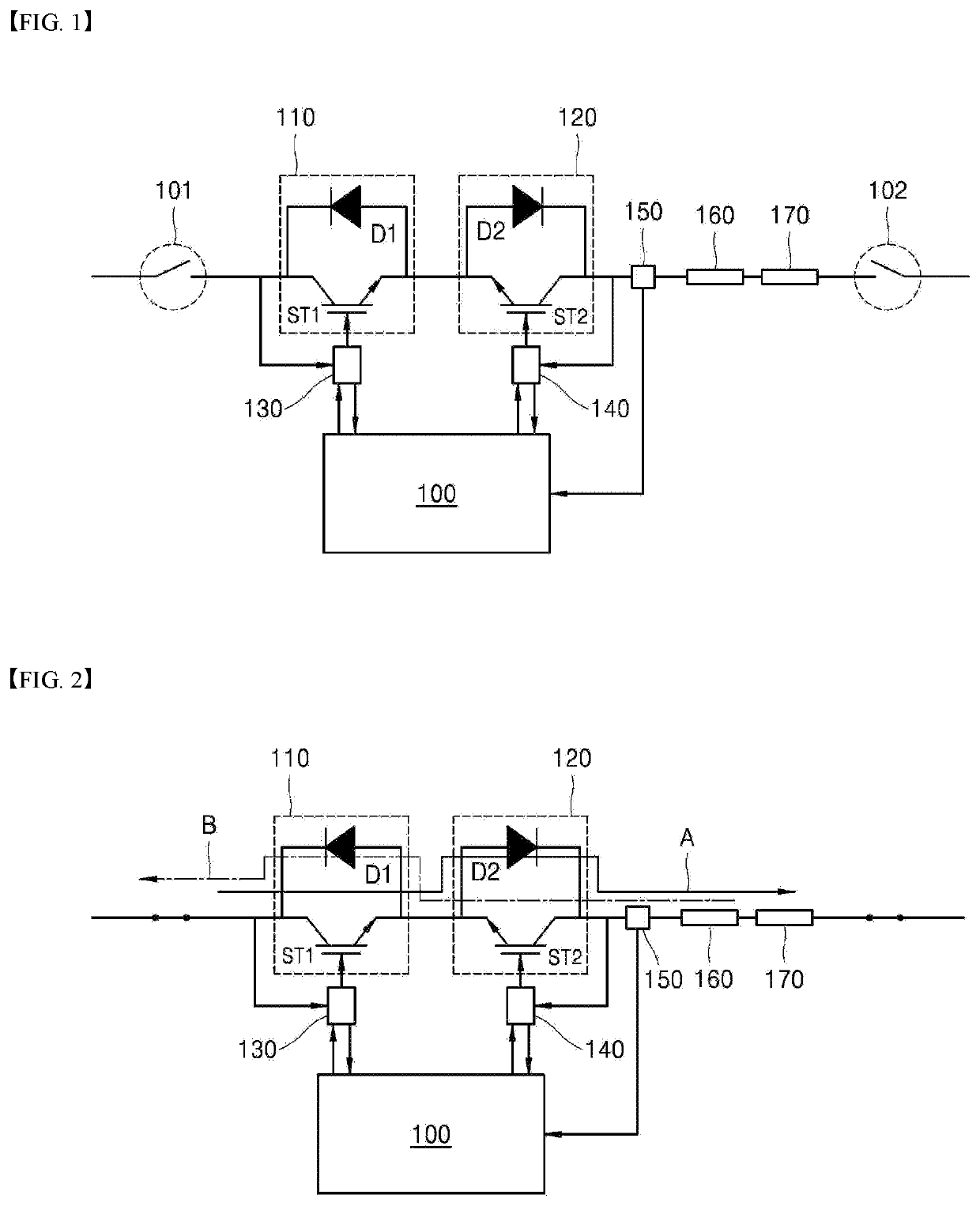
[0035]FIG. 1 is a block diagram showing a configuration of a circuit breaker control module according to the present disclosure.
[0036]The circuit breaker control module shown in FIG. 1 may include a plurality of semiconductor switching units 110 and 120, a controller 100, a plurality of insulated signal transmission elements 130 and 140, at least one cut-off switch 101 and 102, at least one inductance 160, at least one overcurrent prevention fuse 170, and a first current amount detector 150.
[0037]Specifically, each of the plurality of semiconductor switching units 110 and 120 is disposed at a power system, or a power transmission and distribution line. The semiconductor switching units 110 and 120 may cut off current flow in the power transmission and distribution line using a semiconductor switching element for power, or may switch a current flow direction in the power transmission and distribution line.
[0038]To this end, among the plurality of semiconductor switching units 110 and...
second embodiment
[0078]FIG. 5 is a block diagram showing a configuration of a circuit breaker control module according to the present disclosure.
[0079]The circuit breaker control module shown in FIG. 5 may further include a second current amount detector 152 placed on the input terminal or the output terminal of the first semiconductor switching unit 110 among the plurality of semiconductor switching units 110 and 120 connected in a series manner to the power transmission and distribution line.
[0080]The second current amount detector 152 may detect in real time the amount of current flowing in the input terminal or the output terminal of the first semiconductor switching unit 110, and may transmit a detection signal corresponding to the detected current amount to the controller 100.
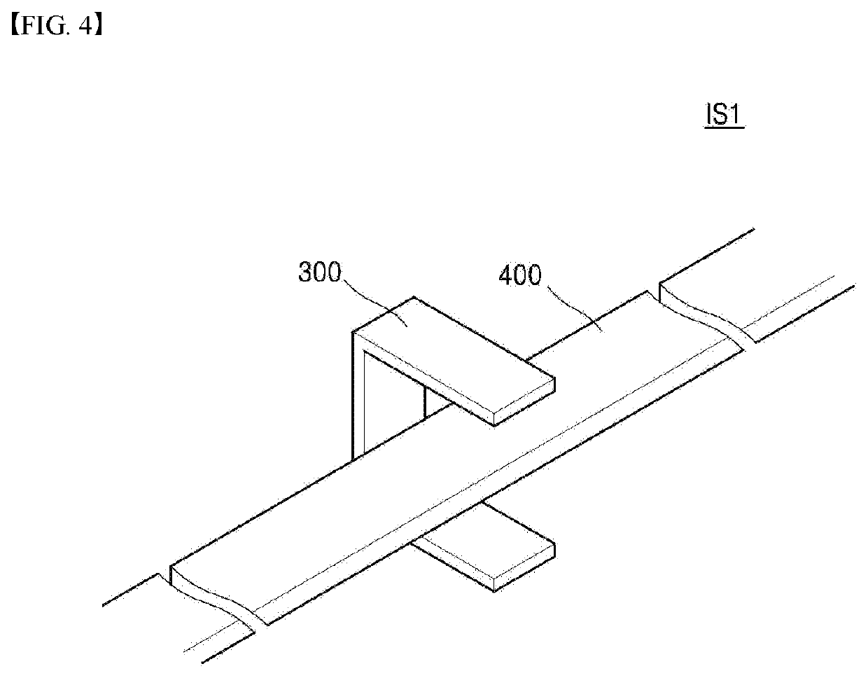
[0081]The second current amount detector 152 may detect a electromagnetic field generated from the input terminal or the output terminal of the first semiconductor switching unit 110 using a Hall sensor 300 spaced by a pr...
third embodiment
[0083]FIG. 6 is a block diagram showing a configuration of a circuit breaker control module according to the present disclosure.
[0084]As shown in FIG. 6, the circuit breaker control module may further include a first short-circuit generator 209, a second short-circuit generator 210, a third short-circuit generator 211, a first voltage detector SV1, and a second voltage detector SV2.
[0085]In this connection, the first short-circuit generator 209 is connected to and disposed between a second ground voltage source and the input terminal or the output terminal of the second semiconductor switching unit 120 among the plurality of semiconductor switching units 110 and 120 connected in a series manner to the power transmission and distribution line. The first short-circuit generator 209 is connected in a parallel manner to the second semiconductor switching unit 120. The first short-circuit generator 209 includes a metaloxidevaristor. Accordingly, when the surge voltage occurs in the inp...
PUM
Abstract
The circuit breaker control module of the present disclosure comprises: a plurality of semiconductor switching units for blocking current flows of transmission distribution lines or performing switching operations so as to switch the current flow directions; a control unit for controlling the turn-on / turn-off operation of each semiconductor switching unit by transmitting a trip signal to each of the plurality of semiconductor switching units; and a plurality of insulation type signal transmission element units which are provided between the plurality of semiconductor switching units and the control unit such that the semiconductor switching units and the control unit are insulated, and which transmit the trip signal from the control unit to each of the plurality of semiconductor switching units, and thus the presently disclosed circuit breaker control module can reduce the risk of accidents due to an electrical arc and increase the stability and reliability of the control unit.
Description
FIELD[0001]The present disclosure relates to a circuit breaker control module that cuts off failure current of a power system or the power transmission and distribution line. More specifically, the present disclosure relates to a circuit breaker control module that includes an electronic semiconductor switching structure to reduce risk of accident due to an arc, and maintains a control circuit for controlling the circuit breaker in an insulated state, thereby to increases stability and reliability thereof.DESCRIPTION OF RELATED ART[0002]When a failure occurs in a power system, a power transmission and distribution line, the failure current is cut off using a DC circuit breaker to protect a power device and equipment electrically connected to a failure line. For example, when overvoltage / overcurrent such as surge voltage occurs in the power transmission and distribution line, a controller or a relay that has detected the overvoltage / overcurrent supplies a trip signal to the circuit b...
Claims
Application Information
Patent Timeline
Application Date:The date an application was filed.
Publication Date:The date a patent or application was officially published.
First Publication Date:The earliest publication date of a patent with the same application number.
Issue Date:Publication date of the patent grant document.
PCT Entry Date:The Entry date of PCT National Phase.
Estimated Expiry Date:The statutory expiry date of a patent right according to the Patent Law, and it is the longest term of protection that the patent right can achieve without the termination of the patent right due to other reasons(Term extension factor has been taken into account ).
Invalid Date:Actual expiry date is based on effective date or publication date of legal transaction data of invalid patent.

