Motor control device and motor system

Inactive Publication Date: 2020-07-30
DENSO CORP
View PDF0 Cites 0 Cited by
  • Summary
  • Abstract
  • Description
  • Claims
  • Application Information

AI Technical Summary

Benefits of technology

[0008]With the above configuration, the control subject is the two-phase motor that obtains the combined torque of the A-phase motor portion and the B-phase motor portion as the output torque. The high-order harmonic current of at least one of “4n+1”th-order and “4n−1”th-order is set when superimposing a high-order harmonic current on the fundamental wave current of the A-phase drive current and the B-phase drive current. This reduces the component of “4n”th-order (“n

Problems solved by technology

However, a simple superimposition of harmonic current will generate new torque pulsation in a

Method used


Image

  • Motor control device and motor system
  • Motor control device and motor system
  • Motor control device and motor system

Examples


Example

First Comparative Example

[0054]The first comparative example in which the A-phase drive current Ia and the B-phase drive current Ib are the sinusoidal fundamental wave currents will now be described with reference to FIGS. 7A and 7D. The A-phase motor portion MA and the B-phase motor portion MB, which form the motor M of the control subject, are configured to have a phase difference of 90 degrees in electrical angle. Accordingly, the phase difference of the A-phase drive current Ia and the B-phase drive current Ib in the first comparative example is generally set to 90 degrees.

[0055]The current waveforms shown in FIG. 7A indicate that when the A-phase drive current Ia and the B-phase drive current Ib are the sinusoidal fundamental wave currents, the phase difference is 90 degrees. As shown in FIG. 7B, in a frequency analysis of the current waveforms using a Fourier transform (current FFT), the A-phase drive current Ia and the B-phase drive current Ib are the fundamental wave current...

Example

Second Comparative Example

[0064]A second comparative example in which the A-phase drive current Ia and the B-phase drive current Ib are the sinusoidal fundamental wave currents (no superimposition of high-order harmonic current) and the phase difference is set to 82 degrees, which is smaller than 90 degrees, will now be described with reference to FIGS. 8A to 8D.

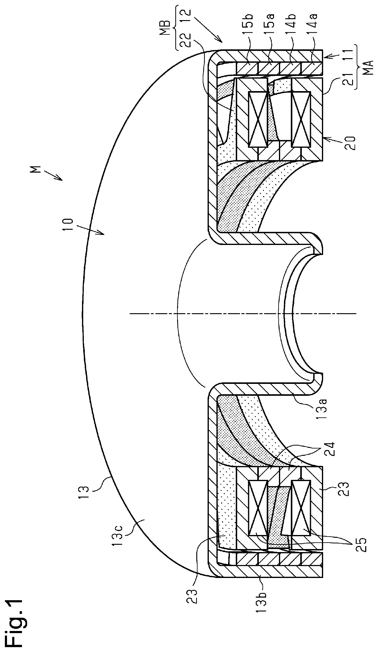
[0065]As described above, the A-phase motor portion MA and the B-phase motor portion MB that form the motor M, which is subject to control, have a phase difference of 90 degrees in electrical angle in terms of the structure. Thus, the phase difference of the A-phase drive current Ia and the B-phase drive current Ib is generally 90 degrees in electrical angle. Further, the present embodiment employs a structure in which the second stator cores 24 of the A-phase stator portion 21 and the B-phase stator portion 22 forming the A-phase motor portion MA and the B-phase motor portion MB are in contact with each other to reduce the ...


PUM


Abstract

A motor control device controls a two-phase motor. The two-phase motor obtains a combined torque, which serves as an output torque. The A-phase and B-phase motor portions being joined having a phase difference in terms of structure. The motor control device sets each of A-phase and B-phase drive currents supplied to the A-phase and B-phase motor portions to control the two-phase motor. The motor control device includes a fundamental wave setting unit that sets a sinusoidal fundamental wave current of the A-phase and B-phase drive currents, and a superimposing wave setting unit that sets a high-order harmonic current superimposed on the fundamental wave current. The superimposing wave setting unit sets the high-order harmonic current of at least one of “4n+1”th-order and “4n−1”th-order to reduce a component of “4n”th-order in torque pulsation of the combined torque, and “n” is a natural number.

Description

[0001]The present application claims priority from Japanese Patent Application No. 2017-121402 filed on Jun. 21, 2017, the entire contents of which are incorporated by reference herein.TECHNICAL FIELD[0002]The present disclosure relates to a motor control device and a motor system that execute harmonic current superimposing control.BACKGROUND ART[0003]A known motor control device executes control for superimposing a harmonic current on a drive current to reduce torque pulsation of a motor. For example, Patent Document 1 discloses a power generation system for reducing torque pulsation by superimposing harmonic currents.PRIOR ART LITERATUREPatent Literature[0004]Patent Document 1: Japanese Laid-Open Patent Publication No. 2015-70781SUMMARY OF THE INVENTION[0005]The superimposition of harmonic currents reduces torque pulsation in the order that is subject to torque pulsation reduction. However, a simple superimposition of harmonic current will generate new torque pulsation in an order...

Claims


Application Information

Patent Timeline
IPC IPC(8): H02P6/10H02P23/04
CPCH02P23/04H02P6/10H02P25/04H02P6/26
Inventor SHIMADA, KAZUNORIUCHIDA, TOSHIHIROTAKEMOTO, YOSHIAKI
Owner DENSO CORP
Why Eureka
Try Eureka