Permanent-magnetic type rotary electric machine

Active Publication Date: 2010-09-30
MITSUBISHI ELECTRIC CORP
View PDF9 Cites 20 Cited by
  • Summary
  • Abstract
  • Description
  • Claims
  • Application Information

AI Technical Summary

Benefits of technology

[0011]According to the present invention, even when magnetomotive force harmonics exist and higher harmonic components are contained in a no-load induced vol

Problems solved by technology

Accordingly, when the motor 34 generates large torque pulsation, it is impossible to obtain a smooth steering feeling.
For example, it is unevenness of torque occurring even when the waveform of current flowing through the armature winding is a sine wave.
In the conventional permanent-magnetic type r

Method used


Image

  • Permanent-magnetic type rotary electric machine
  • Permanent-magnetic type rotary electric machine
  • Permanent-magnetic type rotary electric machine

Examples


Example

First Embodiment

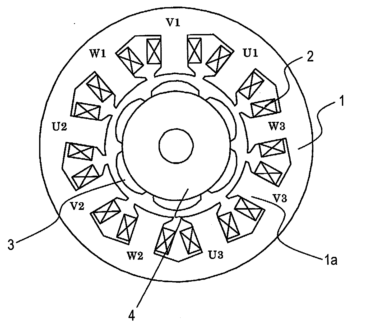
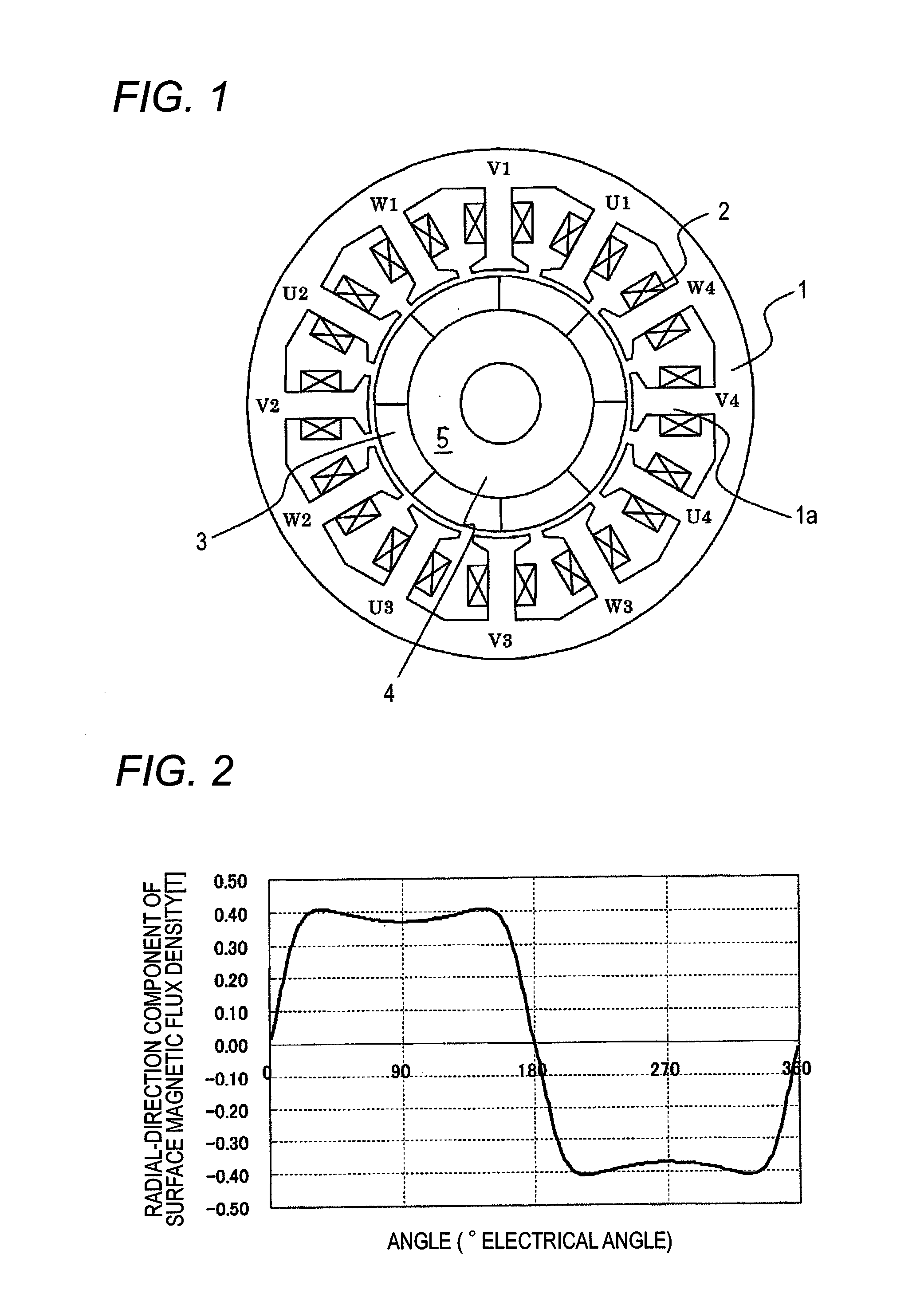
[0034]FIG. 1 is a cross-sectional view showing a permanent-magnetic type rotary electric machine to be implemented in the present invention. A stator iron core 1 is constructed by laminating electromagnetic steel plates, and teeth 1a projecting radially from the annular iron core are arranged on the annular iron core at an equal interval. In FIG. 1, the number of teeth is set to 12. Furthermore, an armature winding 2 is wound around each tooth 1a.

[0035]The armature winding 2 comprises three-phase windings, and when these windings are defined as U-phase, V-phase and W-phase, the arrangement of the armature winding is set like U1, V1, W1, U2, V2, W2, U3, V3, W3, U4, V4 and W4 as indicated at the roots of the teeth 1a of FIG. 1. Here, the alphabets represent the respective phases, and the numerals are expediently allocated to discriminate the armature windings whose arrangements are different although they have the same phase. U1, U2, U3, U4 may be connected to one ano...

Example

[0040]In the conventional example 1 and the conventional example 2 of FIG. 4, the phase of the fifth higher harmonic wave is substantially equal to zero, however, the phase of the seventh higher harmonic wave is equal to about 180°, that is, the phase concerned is substantially inverted. On the other hand, in the present invention, the phases of the fifth and seventh higher harmonic waves are equal to about 180°, that is, the phases thereof are substantially coincident with each other. FIG. 5 shows measurement results of sixth-order components of the torque pulsation for the these three kinds of permanent-magnetic type rotary electric machines. It is apparent from FIG. 5 that the present invention can reduce the torque pulsation to about one third of that of the conventional example 1 and to about a half of that of the conventional example 2.

[0041]Accordingly, it has been confirmed that even in the case of a radial anisotropic ring magnet containing many magnetomotive force harmonic...

Example

Second Embodiment

[0055]In the first embodiment, the present invention is applied to the motor in which the number of poles is set to 8 and the number of teeth, that is, the number of slots is set to 12. In the second embodiment, the present invention is likewise applied to other examples. FIG. 11 shows an example in which the present invention is applied to a motor having six poles and nine slots, FIG. 12 shows an example in which the present invention is applied to a motor having ten poles and 12 slots, and FIG. 13 shows an example in which the present invention is applied to a motor having 14 poles and 12 slots.

[0056]FIG. 11 shows the motor having six poles and nine slots. With respect to a permanent-magnetic type rotary electric machine in which the relationship between the pole number m of the magnet and the slot number n of the stator satisfies 2:3 as in the case of the motor shown in FIG. 11, it trends to have a large magnetomotive force higher harmonic based on the armature w...


PUM


Abstract

A permanent-magnetic type rotary electric machine includes a stator having teeth that are arranged in the peripheral direction thereof and around which armature windings of plural phases are wound, and a rotor having plural permanent magnets arranged so that the poles of the permanent magnets are alternately different in the peripheral direction thereof, higher harmonic waves being contained in a no-load induced voltage waveform. A (6p−1)-th higher harmonic wave and a (6p−1)-th higher harmonic wave (p represents a positive integer) when an electrical angle of 360° is set as a fundamental wave in the no-load induced voltage waveform are made substantially coincident with each other in amplitude and phase.

Description

BACKGROUND OF THE INVENTION[0001]1. Field of the Invention[0002]The present invention relates to a permanent-magnetic type rotary electric machine, and for example it relates to a motor used in an electrical power steering device for a vehicle.[0003]2. Description of the Related Art[0004]FIG. 20 is a schematic diagram showing a general electrical power steering device for a vehicle. In FIG. 20, the electrical power steering device is provided with a column shaft 31 for transmitting steering force from a steering wheel 30. A worm gear 32 is connected to the column shaft 31, and it transmits the output (torque, rotational speed) of a permanent-magnetic motor 34 driven by a controller 33 while changing the rotational direction to the vertical direction and decelerates the motor at the same time to increase the assist torque. Reference numeral 35 represents a handle joint, and it can transmit the steering force and also change the rotational direction. Reference numeral36 represents a s...

Claims


Application Information

Patent Timeline
IPC IPC(8): H02K1/06
CPCH02K1/278H02K2201/06H02K29/03H02K21/16
Inventor AKUTSU, SATORUNISHIKAWA, HIDEYAASAO, YOSHIHITONAKANO, MASATSUGU
Owner MITSUBISHI ELECTRIC CORP
Why Eureka
Try Eureka