Solar energy systems

a solar energy system and solar energy technology, applied in the direction of electric lighting with batteries, electric circuit arrangements, with built-in power, etc., can solve the problems of imposing large and undesirable force loads on the structure(s)

Active Publication Date: 2015-06-11
MERINGER JAMES A
View PDF13 Cites 28 Cited by
  • Summary
  • Abstract
  • Description
  • Claims
  • Application Information

AI Technical Summary

Benefits of technology

[0021]For purposes of summarizing the invention, certain aspects, advantages, and novel features of the invention have been described herein. It is to be understood that not necessarily all such advantages may be achieved in accordance with any one particular embodiment of the invention. Thus, the invention may be embodied or carried out in a manner that achieves or optimizes one advantage or group of advantages as taught herein without necessarily achieving other advantages as may be taught or suggested herein. The features of the invention which are believed to be novel are particularly pointed out and distinctly claimed in the concluding portion of the specification. These and other features, aspects, and advantages of the present invention will become better understood with reference to the following drawings and detailed description.

Problems solved by technology

Furthermore, during heavy wind, such large collector panel(s) may impose large and undesirable force loads on the structure(s) to which they are attached.

Method used


Image

  • Solar energy systems
  • Solar energy systems
  • Solar energy systems

Examples


Embodiment Construction

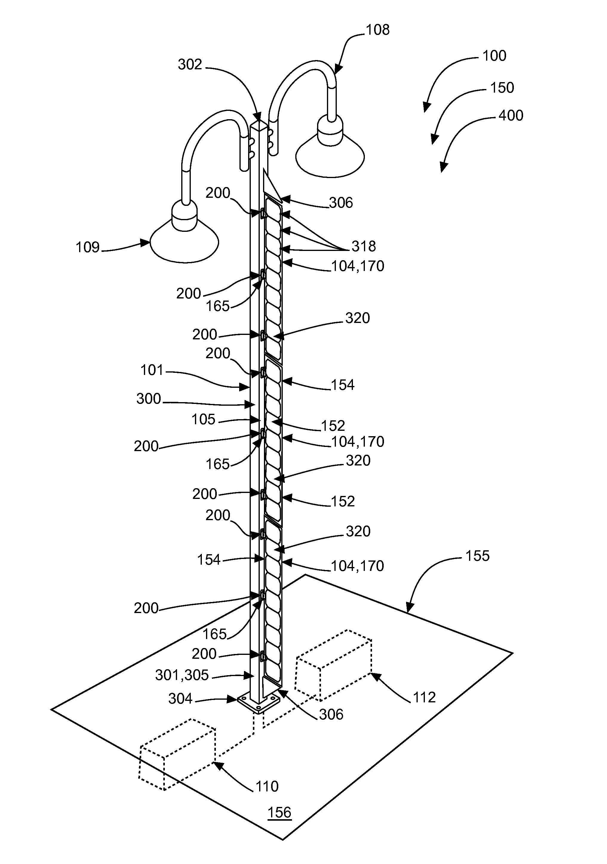
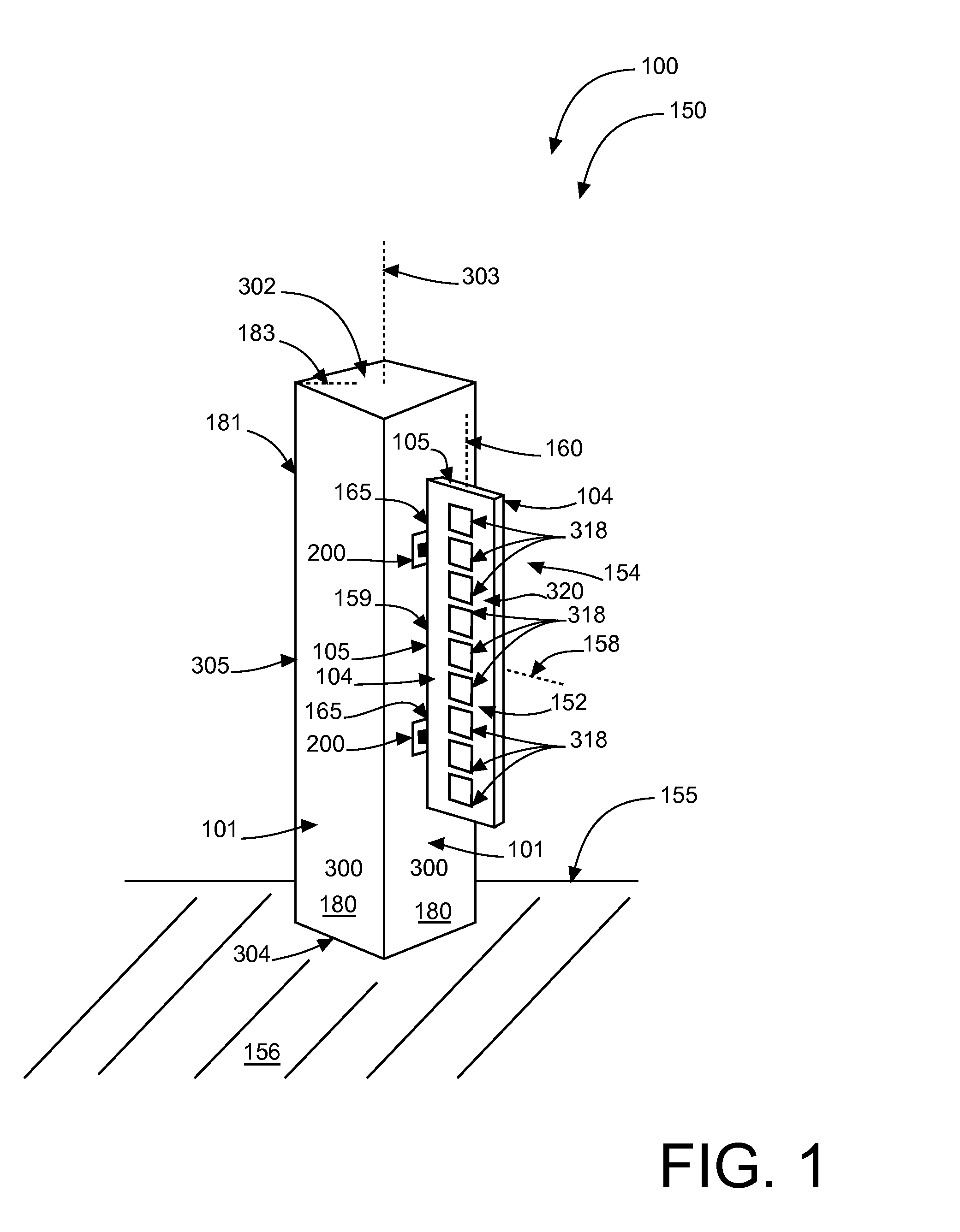
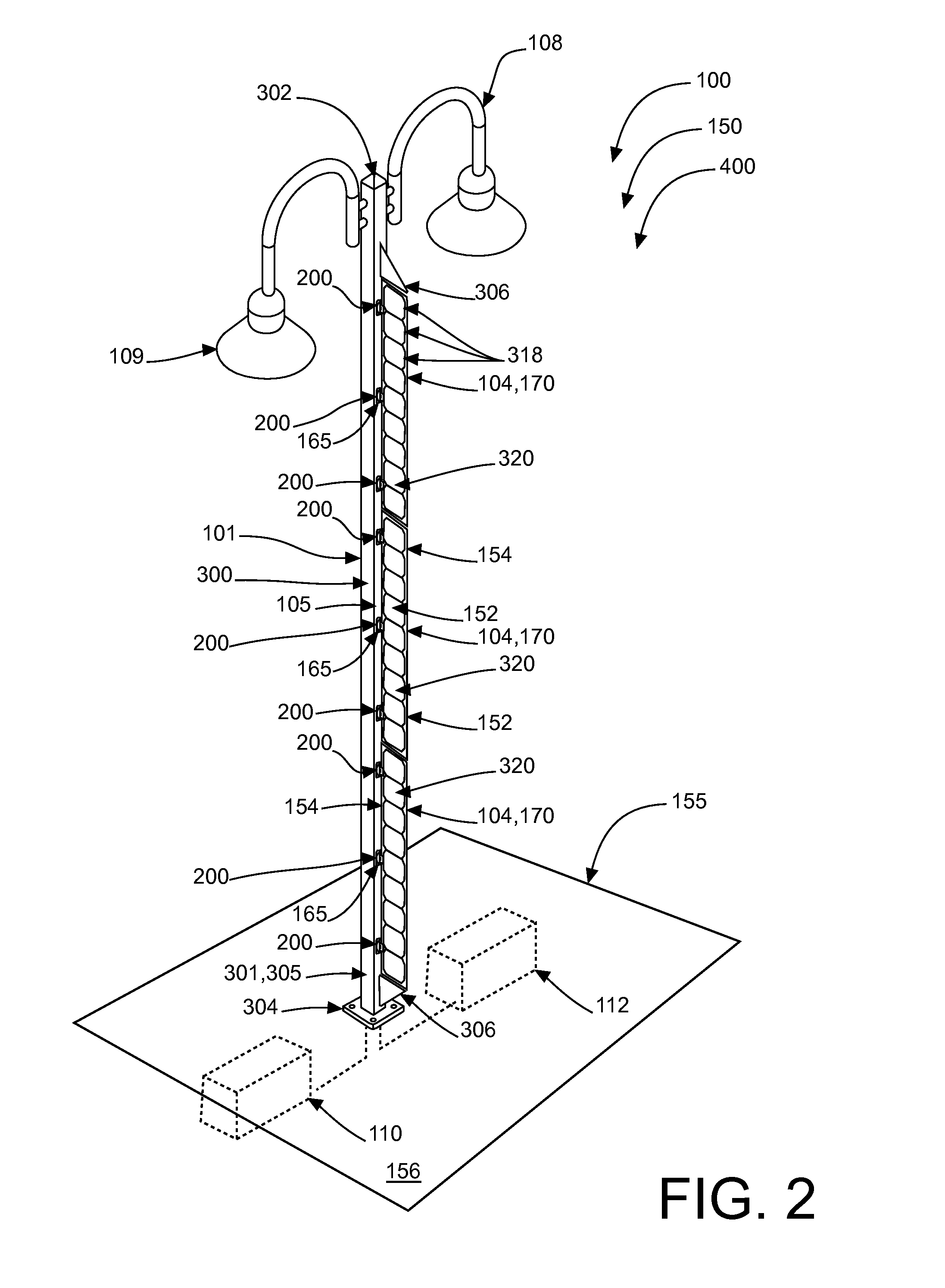
[0032]Illustrated in FIGS. 1-6, and in accordance with preferred embodiments of the invention, is an improved solar energy system 100 utilizing a solar energy collector mounting assembly 150, comprising at least one solar active component having a flat planar body (exemplified by solar fin 104), inherently comprising first (“front”) and second (“back”) opposing faces 152, 154, respectively; first (“horizontal”) and second (“vertical”) planar axes 158, 160, respectively (see FIGS. 2 and 4A), which are orthogonal one another; and a perimeter frame 105 surrounding faces 152, 154. Solar fin 104 is mounted to at least one support 101 having a mounting surface 180 (see FIG. 1), with inherent vertical axis 160 of solar fin 104 preferably essentially orthogonal to the surface 155 of the ground 156 (or the horizon), and preferably with inherent horizontal axis 158 of solar fin 104 essentially orthogonal to or radially aligned with surface 180. This provides substantially equal direct sun exp...


PUM


Abstract

Improved solar energy system including an improved solar collector mounting assembly, preferably comprises a bi-facial solar active component mounted with its solar active face(s) orthogonal to the ground/horizon, at or near its perimeter frame. According to certain embodiments, the mounting assembly allows the fin to oscillate with respect to a fixed mounting position in response to displacing forces. Additionally, the solar energy system may be utilized to retrofit an existing energy operating system, wherein the solar powered system can interact in a hybrid fashion with the existing energy source of the retrofitted system.

Description

CROSS-REFERENCE TO RELATED APPLICATION(S)[0001]The present application is related to and claims priority from Provisional Application Ser. No. 61 / 914,149 filed Dec. 10, 2013, Provisional Application Ser. No. 61 / 934,404 filed Jan. 31, 2014, Provisional Application Ser. No. 61 / 987,183, filed May 1, 2014, and Provisional Application Ser. No. 62 / 007,276, filed Jun. 3, 201, the contents of all of which are incorporated herein by this reference.COPYRIGHT NOTICE[0002]A portion of the disclosure of this patent document contains material which is subject to copyright protection. The copyright owner has no objection to the facsimile reproduction by anyone of the patent document or the patent disclosure, as it appears in the Patent and Trademark Office patent file or records, but otherwise reserves all copyright rights whatsoever. 37 CFR 1.71(d).BACKGROUND OF THE INVENTION[0003]The following includes information that may be useful in understanding the present invention(s). It is not an admissi...

Claims


Application Information

Patent Timeline
Patent Type & Authority Applications(United States)
IPC IPC(8): H02S20/20F21S8/08H02J7/35F21S9/03H02S10/20H02S20/10
CPCH02S20/20H02S10/20F21S8/085H02J7/35F21S9/035H02S20/10F21V23/0442F21W2131/103F24S25/10F24S25/632F24S30/422F24S2020/16F24S2030/16H02S40/38Y02B20/72Y02E10/47Y02E10/50Y02E70/30
Inventor MERINGER, JAMES A.
Owner MERINGER JAMES A
Why Eureka
Try Eureka