Electric System Stabilizing System for Aircraft

a technology of electric system and stabilizing system, which is applied in the direction of energy-efficient board measures, power supply testing, instruments, etc., can solve the problems of engine gear box adversely affected, power supply voltage fluctuation, electric system unstable, etc., and achieve favorable stabilization of electric system and avoid weight increase

Active Publication Date: 2015-06-18
THE BOEING CO +1
View PDF18 Cites 8 Cited by
  • Summary
  • Abstract
  • Description
  • Claims
  • Application Information

AI Technical Summary

Benefits of technology

[0029]As described above, according to the present invention, it achieves an advantageous effect that provide an electric system stabilizing system for an aircraft, which is capable of favorably stabilizing an electric system while avoiding a weight increase, in an aircraft including the electric system which is electrically driven mainly by AC power.

Problems solved by technology

It is known that with a progress of the MEA, a change (fluctuation) in a power supply voltage tends to occur, and the electric system tends to be unstable.
In addition, the electric power is returned to a generator provided in an engine, and thereby an engine gear box might be adversely affected due to back rush.
Or, if power loads supplied with the electric power from the electric system, (devices mounted in the aircraft and supplied with electric power from the electric system) increase temporarily, a significant voltage decrease (drop) might be generated.
However, in the above stated conventional configurations, a weight of the aircraft might probably increase.
Therefore, the size of the controller of the actuator increases and heat generated increases, which causes a need for a large-sized heat radiator.
Because of incorporation of the large-sized controller and the large-sized heat radiator into the aircraft, the weight of the aircraft increases.
In the latter configuration, the size of the AC power generator increases due to the increase in the power generation capacity, and therefore, the weight of the aircraft increases.
Moreover, in the former configuration, although the heat radiator is provided, unnecessary heat generation occurs.

Method used


Image

  • Electric System Stabilizing System for Aircraft
  • Electric System Stabilizing System for Aircraft
  • Electric System Stabilizing System for Aircraft

Examples


modified example

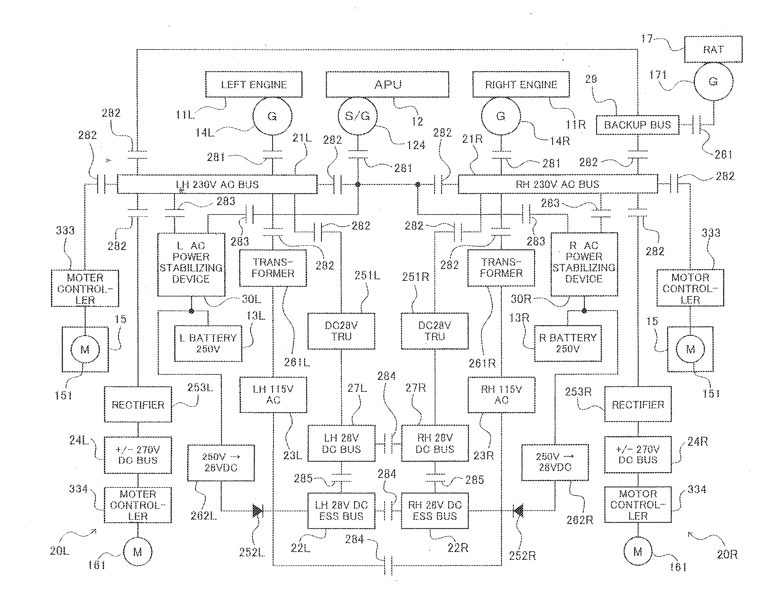
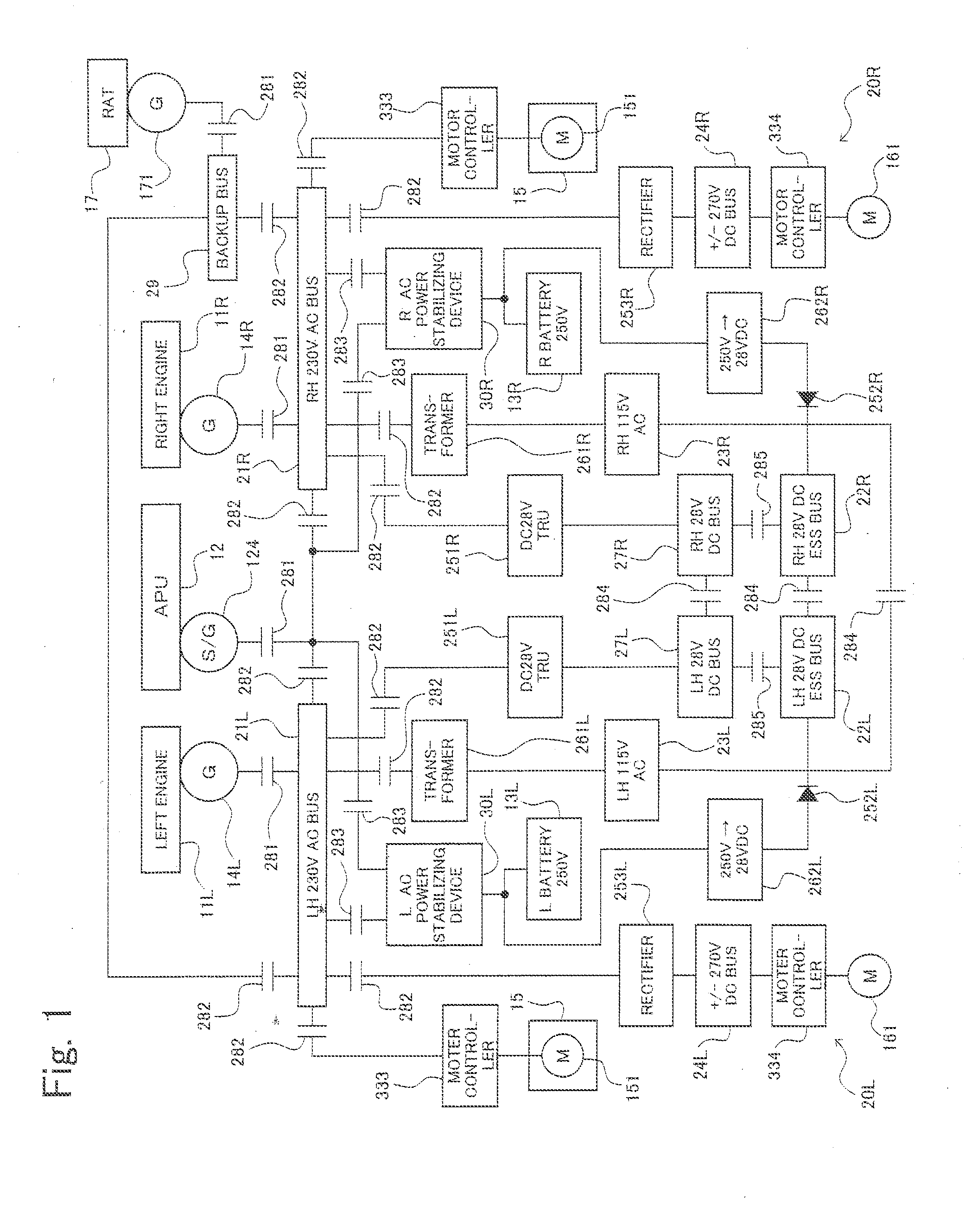
[0197]Although in the present embodiment, the secondary batteries 13L, 13R having the rated voltage of 250V are illustrated as the DC power supplies, the present invention is not limited to this. For example, the DC power supplies may be capacitors having an equally rated voltage, or a combination of the capacitors and secondary batteries. As an example of the capacitors, electric double-layer capacitors having a high capacity, which are named ultra capacitors, may be used. Thus, in the present invention, the DC power supplies are not limited to the secondary batteries 13L, 13R so long as they can absorb the regenerative power from the electric devices such as the control surface actuator 15, and transiently supply necessary electric power.

[0198]A plurality of secondary batteries and / or capacitors may be combined to form DC power supplies provided that the weight of the aircraft is not increased excessively. In a case where the DC power supplies are the capacitors, stabilization of ...


PUM


Abstract

An electric system of an aircraft includes a power stabilizing device connected to a primary AC bus and a secondary battery. The secondary battery has a rated voltage which allows the secondary battery to absorb regenerative power from a control surface actuator. Based on a voltage and a frequency in the primary AC bus, charging / discharging of the secondary battery is controlled to stabilize the electric system.

Description

TECHNICAL FIELD[0001]The present invention relates to an electric system stabilizing system for an aircraft. Particularly, the present invention relates to an electric system stabilizing system for an aircraft, which is capable of stabilizing an electric system which includes an AC power supply and a DC power supply and is electrically driven mainly by AC power.BACKGROUND ART[0002]Typically, as power systems for an aircraft, three kinds of systems, which are a hydraulic system, a breed air system, and an electric system, are incorporated into the aircraft. The hydraulic system is employed for the operation of landing gears, control surfaces, etc. The breed air system is employed for the operation of air conditioning devices, pressure application devices, de-icing devices, and others, in the interior of the aircraft. The electric system is employed for the operation of electric devices and electronic devices. In recent years, there has been a trend that at least a portion of the hydr...

Claims


Application Information

Patent Timeline
Patent Type & Authority Applications(United States)
IPC IPC(8): B60R16/03B64D41/00
CPCB64D41/007B60R16/03H02J4/00G01R31/42G01R31/008Y02T50/50G05B13/02
Inventor IWASHIMA, ATSUSHISUGIMOTO, KAZUSHIGEMATSUO, KAZUYABREIT, JOSEPH S.NOZARI, FARHAD
Owner THE BOEING CO
Why Eureka
Try Eureka