
Electric system stabilizing system for aircraft

a technology of electric system and stabilizing system, which is applied in the direction of energy-saving board measures, electric devices, transportation and packaging, etc., can solve the problems of increasing the weight of the aircraft, the quantity and number of power loads supplied with electric power from the electric system, and the energy loss of the breeding air system, so as to avoid a weight increase and avoid the effect of affecting the stabilization effect of the electric system

Inactive Publication Date: 2014-07-17
KAWASAKI HEAVY IND LTD +1
View PDF8 Cites 52 Cited by
  • Summary
  • Abstract
  • Description
  • Claims
  • Application Information

AI Technical Summary

Benefits of technology

The present invention provides an electric system stabilizing system for aircraft that can manage the transition between AC and DC power without adding weight or complexity to the system. The system includes a power converter and a boost converter to stabilize the voltage in both the AC and DC power supplies. The system also includes a DC power supply that absorbs regenerative power from the electrified device and stabilizes the power supply by charging and discharging the DC bus based on the voltage in the AC power supply and the DC power supply. This results in a more stable electric system for the aircraft.

Problems solved by technology

For example, it is known that the breed air system generates a great energy loss.
However, with a progress of the MEA in the aircraft, power loads (devices supplied with electric power from the electric systems) supplied with electric power from the electric systems significantly increase in quantity and number.
This would result in an increase in the weight of the aircraft.
Or, if the power loads to be supplied with the electric power increase in number temporarily, a significant voltage decrease (drop) occurs.
However, Patent Literature 1 does not disclose avoidance or suppressing a change in power supply voltage.
Since the electric system in a general commercial aircraft is electrically driven mainly by AC, a technique intended for the electric system electrically driven mainly by the DC is not applicable to the electric system electrically driven mainly by AC unless it is modified.

Method used


Image

  • Electric system stabilizing system for aircraft
  • Electric system stabilizing system for aircraft
  • Electric system stabilizing system for aircraft

Examples


embodiment 1

Power Systems of Aircraft

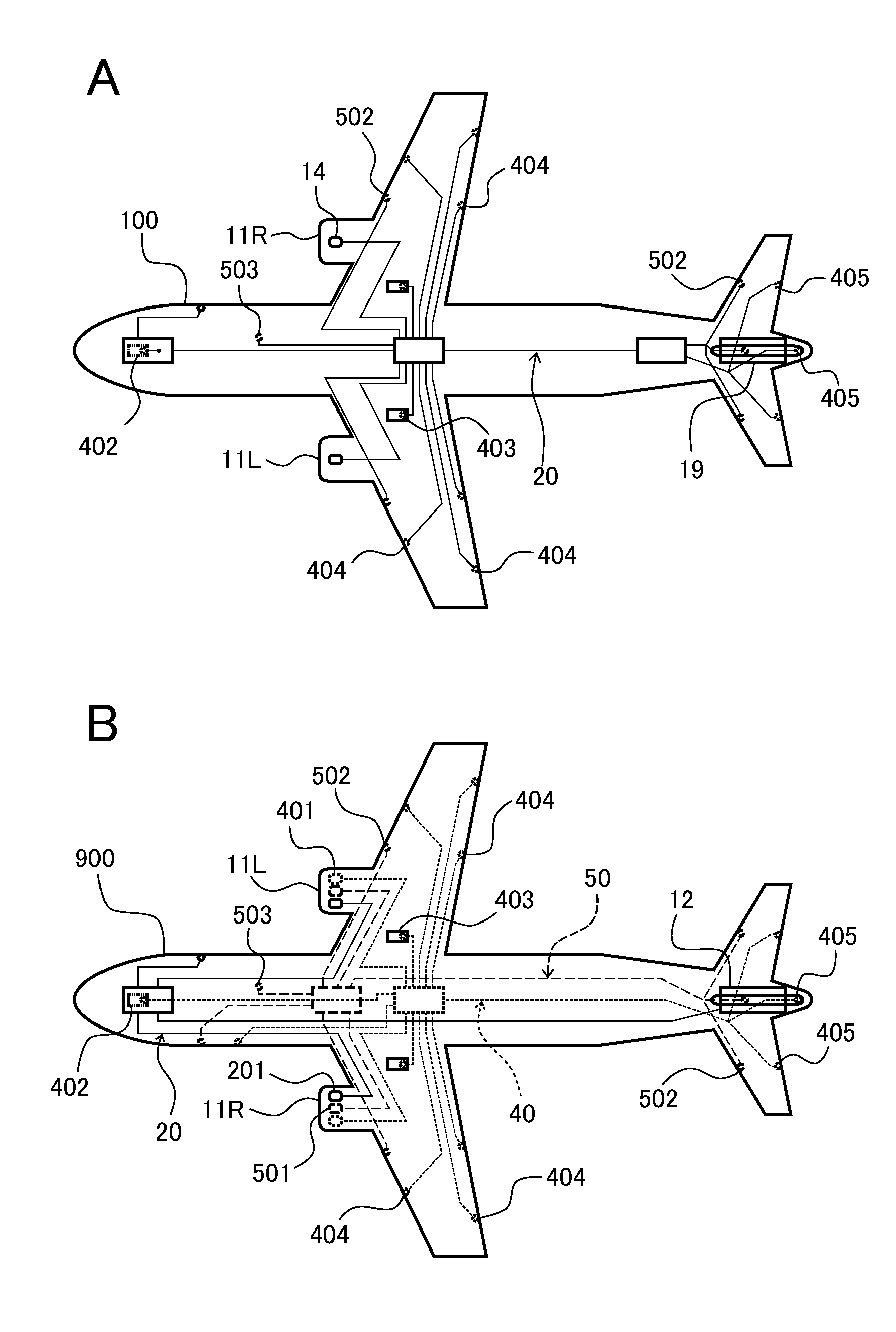
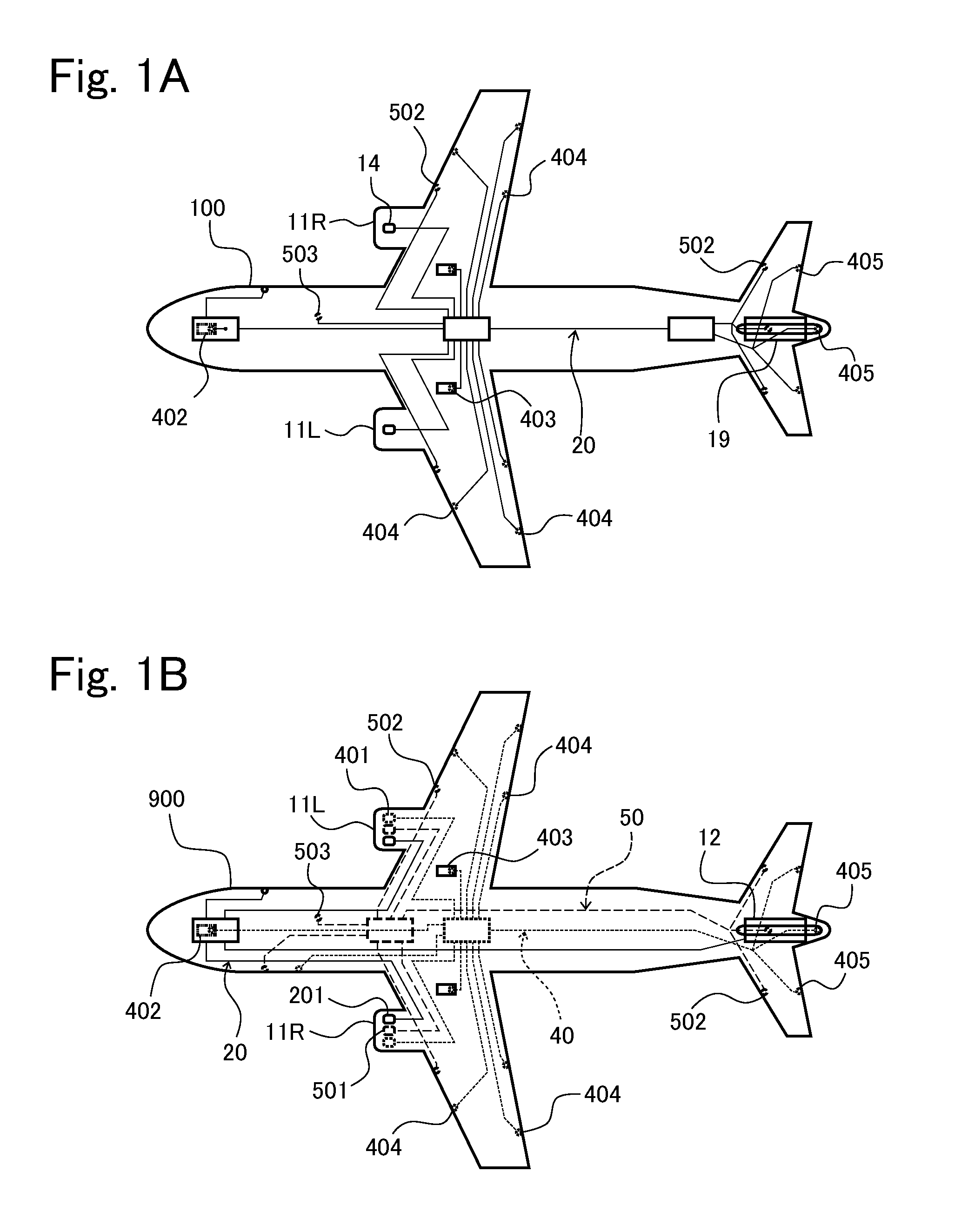
[0046]First of all, a schematic configuration of power systems in an aircraft to which an electric system stabilizing system for an aircraft according to Embodiment 1 of the present invention is applied will be described with reference to FIGS. 1A, 1B. Hereinafter, for easier description, “electric system stabilizing system for an aircraft” will be simply referred to as “stabilizing system”.

[0047]The stabilizing system of the present embodiment is provided in MEA (or AEA) in which at least a portion of a hydraulic system and / or a portion of a breed air system are constructed as electric systems. FIG. 1A shows a schematic configuration of an aircraft 100 in which all of the power systems are constructed as electric systems, and FIG. 1B shows a schematic configuration of a conventional general aircraft 900 including power systems.

[0048]The general aircraft 900 includes a hydraulic system 40 indicated by a dotted line in FIG. 1B and a breed air system 50 indica...

modified example

[0216]Although in the present embodiment, the secondary batteries 13L, 13R having the rated voltage of 250V are illustrated as the DC power supplies, the present invention is not limited to this. For example, the DC power supplies may be capacitors having an equal rated voltage, or a combination of capacitors and secondary batteries. As an example of the capacitor, an electric double-layer capacitor having a high capacity, which is named ultra capacitor, may be used. Thus, in the present invention, the DC power supplies are not limited to the secondary batteries 13L, 13R so long as they can absorb the regenerative power from the power loads 15.

[0217]A plurality of secondary batteries and / or capacitors may be combined to form DC power supplies provided that the weight of the aircraft is not increased excessively. In a case where the DC power supplies are the capacitors, stabilization of the electric system can be achieved but the APU 12 cannot be started. In view of this, to start th...

embodiment 2

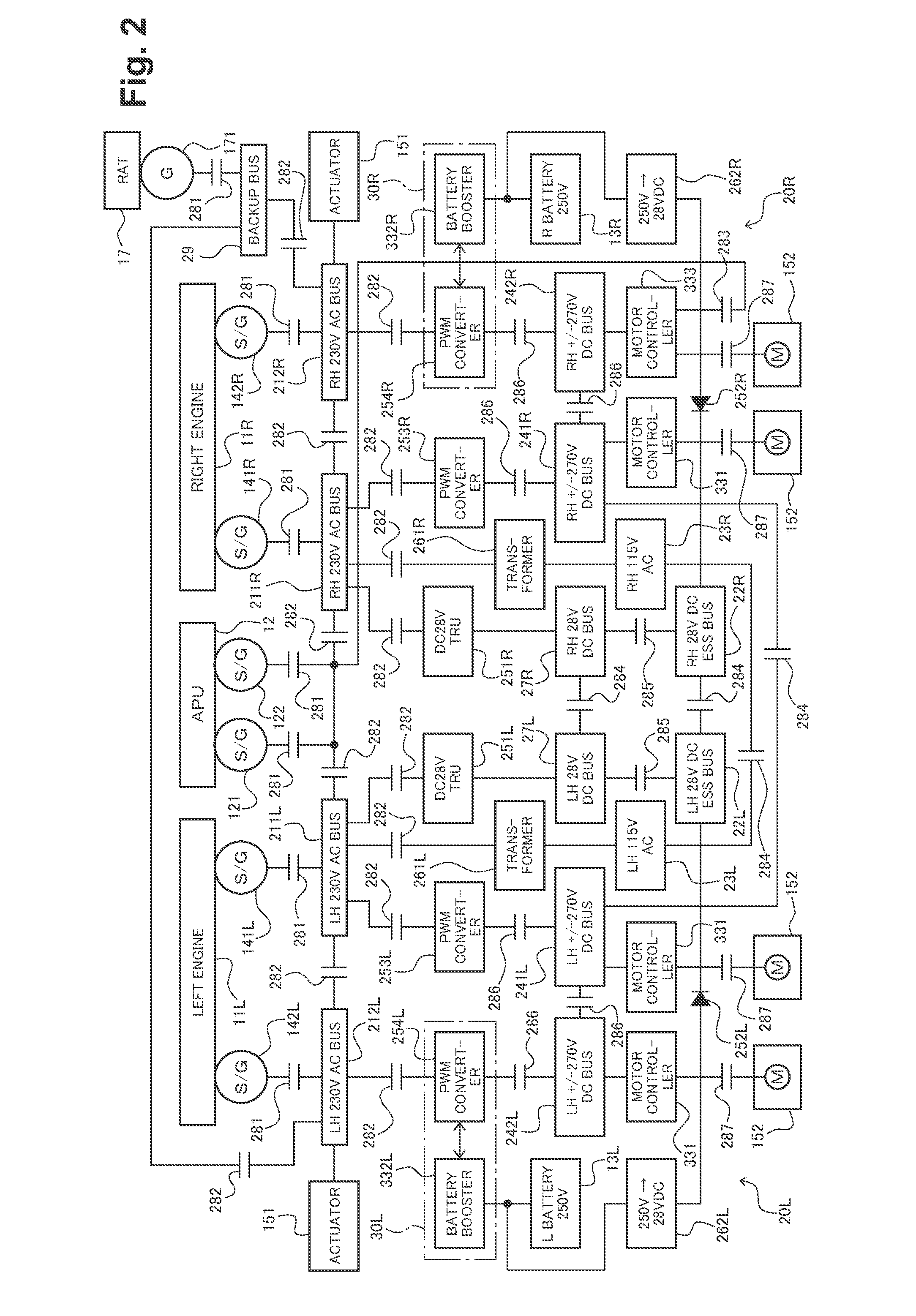
[0223]An electric system stabilizing system for the aircraft according to Embodiment 2 of the present invention has the same configuration as that of the electric system stabilizing system for the aircraft according to Embodiment 1, except that the secondary batteries 13L, 13R are bidirectionally connected to the second DC buses 242L, 242R via the boost converters 332L, 332R (bold-line arrow in FIG. 13) while keeping the ATRUs 255L, 255R, as shown in FIG. 13, instead of replacing the conventional ATRUs by the PWM converters.

[0224]Instead of controlling the electric power by increasing / decreasing the electric power in the second primary AC bus 212L, 212R like Embodiment 1, the DC power supplied to the second DC bus 242L, 242R via the ATRU 255L, 255R is directly controlled to indirectly control the electric power in the second primary AC bus 212L, 212R.

[0225]Specifically, the power stabilizing control section 36 (see FIGS. 3 and 4) monitors a voltage in the second primary AC bus 212L,...


PUM


Abstract

A power stabilizing device in a system includes as a portion of a power converter section, a second PWM converter provided between a second primary AC bus and a second DC bus in an electric system and configured to perform mutual conversion between DC power and AC power. A power stabilizing control section in the power stabilizing device controls charging and discharging of a secondary battery based on a voltage and a frequency in the second primary AC bus, thereby stabilizing the electric system.

Description

BACKGROUND OF THE INVENTION[0001]1. Field of the Invention[0002]The present invention relates to an electric system stabilizing system for an aircraft. Particularly, the present invention relates to an electric system stabilizing system for an aircraft, which is capable of stabilizing an electric system which includes an AC power supply and a DC power supply and is electrically driven mainly based on AC power.[0003]2. Description of the Related Art[0004]Typically, as power systems for an aircraft, three kinds of systems, which are a hydraulic system, a breed air system, and an electric system, are incorporated into the aircraft. The hydraulic system is employed for the operation of landing gears, control surfaces, etc. The breed air system is employed for the operation of air conditioning devices, pressure application devices, de-icing devices, and others, in the interior of the aircraft. The electric system is employed for the operation of electronic devices. In recent years, there...

Claims


Application Information

Patent Timeline
IPC IPC(8): B60R16/03
CPCB60R16/03B64D2221/00Y02T50/50H02J4/00B60L53/00H02J2310/44B60L53/53B60L53/56B60L53/55Y02T10/70Y02T90/12Y02T10/7072Y02T90/14B64D41/007
Inventor IWASHIMA, ATSUSHISUGIMOTO, KAZUSHIGEMATSUO, KAZUYABREIT, JOSEPH S.NOZARI, FARHAD
Owner KAWASAKI HEAVY IND LTD
Learn More