Motorcycle frame structure

a frame structure and motorcycle technology, applied in the direction of cycle equipment, transportation and packaging, cycle, etc., can solve the problem of extremely small load applied to the second bolt resulting from the load applied to the seat rail from above, and achieve the effect of preventing an increase in the weight of the pivot pla

Active Publication Date: 2009-10-01
HONDA MOTOR CO LTD
View PDF13 Cites 11 Cited by
  • Summary
  • Abstract
  • Description
  • Claims
  • Application Information

AI Technical Summary

Problems solved by technology

Therefore, a load applied to the second bolt resulting from a load applied to the seat rail from above becomes extremely small.

Method used


Image

  • Motorcycle frame structure
  • Motorcycle frame structure
  • Motorcycle frame structure

Examples


Embodiment Construction

[0028]A selected exemplary embodiment of the present invention will now be described, with reference to the drawings. Throughout this description, relative terms like “front”, “rear”, “longitudinal,”“crosswise,”“vertical,” and the like are used in reference to a vantage point of an operator of the vehicle, seated on the driver's seat and facing forward. It should be understood that these terms are used for purposes of illustration, and are not intended to limit the invention.

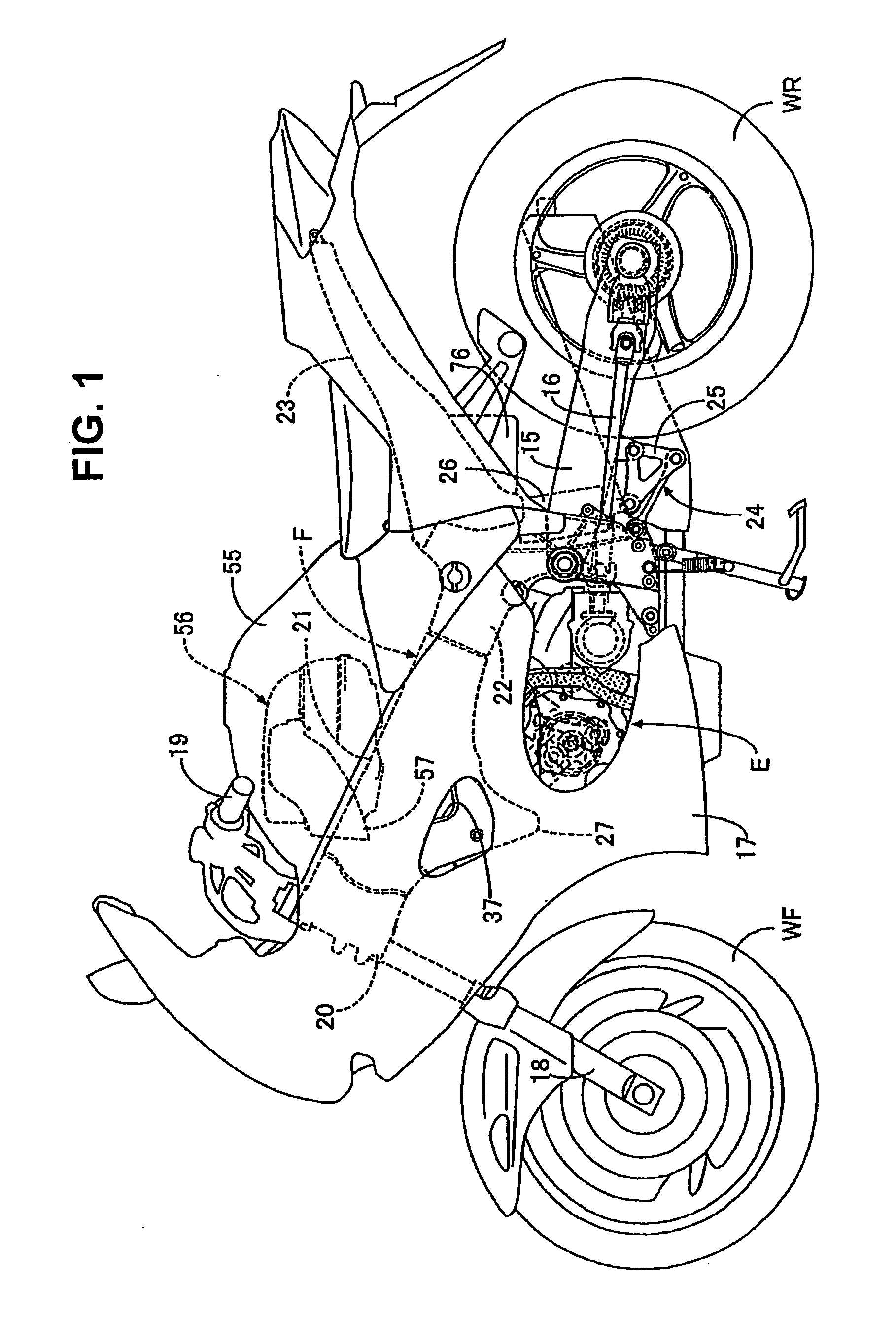
[0029]Referring first to FIG. 1, for example, a 4-cylidner V-type engine E is mounted on a vehicle frame F of a motorcycle. A rear wheel WR is rotatably supported by the rear portion of a swing arm 15 vertically swingably carried by the body frame F. Power of the engine E is transmitted to the rear wheel WR via a drive shaft 16 extending back and forth. A portion of the engine E and the body frame F are covered by a body cover 17, which is mounted to the body frame F.

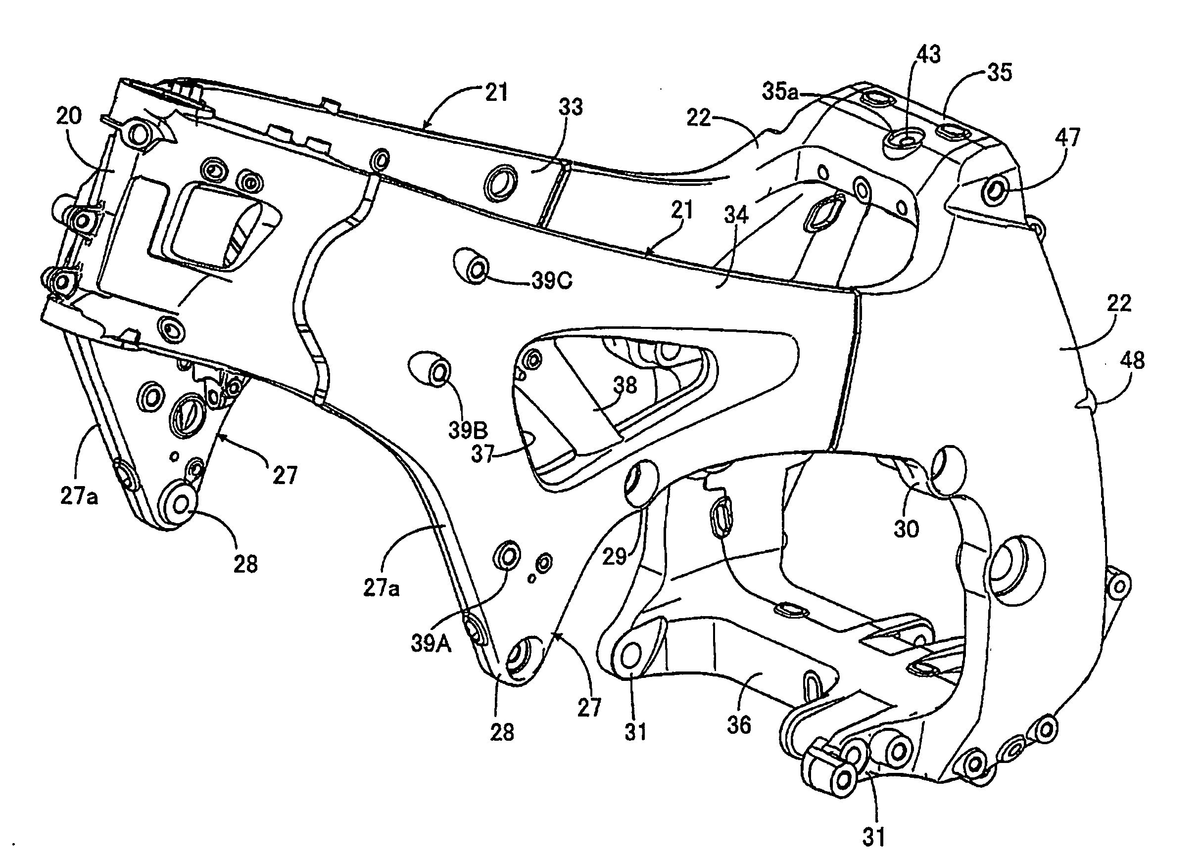
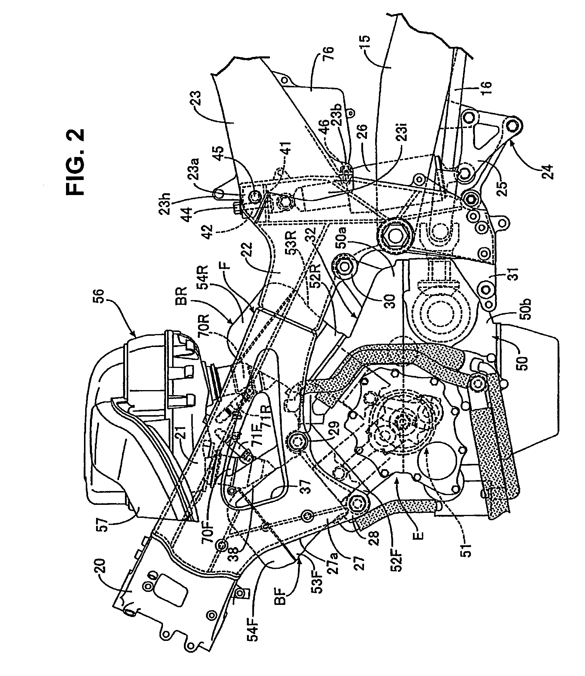
[0030]With additional reference to FIGS. 2 to...


PUM


Abstract

A motorcycle frame structure includes pivot plates at rear portions of left and right main frames extending rearwardly and downwardly from a head pipe. A seat rail is fastened to an upper portion of the pivot plate at two positions which are vertically spaced apart from each other, and also at the front end of the seat rail. A first attachment portion and a second attachment portion are attached to a front end of the seat rail. The first attachment portion is fastened to the pivot plate from the horizontally external side of the seat rail with a first bolt, and laterally overlaps a rear upper lateral surface of the pivot plate. The second attachment portion is fastened to the pivot plate from the rear side of the pivot plate with a second bolt, and overlaps a rear portion of the pivot plate.

Description

CROSS-REFERENCE TO RELATED APPLICATIONS[0001]The present invention claims priority under 35 USC 119 based on Japanese patent application No. 2008-092854, filed on Mar. 31, 2008. The entire subject matter of this priority document, including specification, claims and drawings, is incorporated by reference herein.BACKGROUND OF THE INVENTION[0002]1. Technical Field of the Invention[0003]The present invention relates to a motorcycle frame structure. More particularly, the present invention relates to a body frame of a motorcycle in which a pivot plate, vertically and swingably supporting a front portion of a swing arm which is rotatably supporting a rear wheel at a rear portion, is provided at a rear portion of each of a plurality of main frames extending rearward and downward from a head pipe which is steerably supporting a front fork and a steering handlebar, and a front end of a seat rail is fastened to an upper portion of the pivot plate at two positions of a front end vertically sp...

Claims


Application Information

Patent Timeline
Patent Type & Authority Applications(United States)
IPC IPC(8): B62D21/09
CPCB62K19/12B62K11/04
Inventor MORITA, KENJIHARIU, JUN
Owner HONDA MOTOR CO LTD
Why Eureka
Try Eureka