Lower vehicle-body structure of electric vehicle

a vehicle body and electric vehicle technology, applied in the direction of electric propulsion mounting, transportation and packaging, passenger space, etc., can solve the problems of reduced shift feeling or unintended vibration noise, reduced weight reduction effect, and inability to obtain tunnels, etc., to increase the rigidity, and increase the resistance to lateral collision

Active Publication Date: 2020-11-19
MAZDA MOTOR CORP
View PDF0 Cites 14 Cited by
  • Summary
  • Abstract
  • Description
  • Claims
  • Application Information

AI Technical Summary

Benefits of technology

[0059]According to this configuration, the upper enlarged section is formed separately from the floor cross member. This can form linear ridges as basic parts of the floor cross member and increase resistance to lateral collision. Particularly, left and right floor frames extending in a vehicle front-rear direction are provided below the floor panel, and a part of the floor cross member between the left and right floor frames has higher rigidity than parts located on vehicle-width-direction outer sides of the floor frames, and is formed of one member. The parts located on the vehicle-width-direction outer sides of the floor frames may be formed of a high tensile steel plate having a thickness of 1.0 mm, and the part of the floor cross member between the left and right floor frames may be formed of an ultrahigh tensile steel plate having a thickness of 1.8 mm.
[0060]According to this configuration, lateral collision energy is absorbed by the outer parts of the floor cross member located on the vehicle-width-direction outer sides of the floor frames, and the part of the floor cross member between the left and right floor frames, that is, the basic part is formed of one member, thereby increasing resistance to lateral collision. Particularly, securing portions for the front part of the front seat are formed on opposite sides of the upper enlarged section in the vehicle width direction at the same height as the upper enlarged section.
[0061]This configuration can form linear ridges of the upper enlarged section in the vehicle width direction, increase resistance to lateral collision, and also improve

Problems solved by technology

On the other hand, if desired resistance to front-end collision and a support structure for the center console are ensured by a tunnel-like structure, a weight reducing effect by eliminating the tunnel cannot be obtained.
Thus, the console suppor

Method used


Image

  • Lower vehicle-body structure of electric vehicle
  • Lower vehicle-body structure of electric vehicle
  • Lower vehicle-body structure of electric vehicle

Examples


first embodiment

The First Embodiment

[0084]Now, with reference to the drawings, an embodiment of the present disclosure will be described.

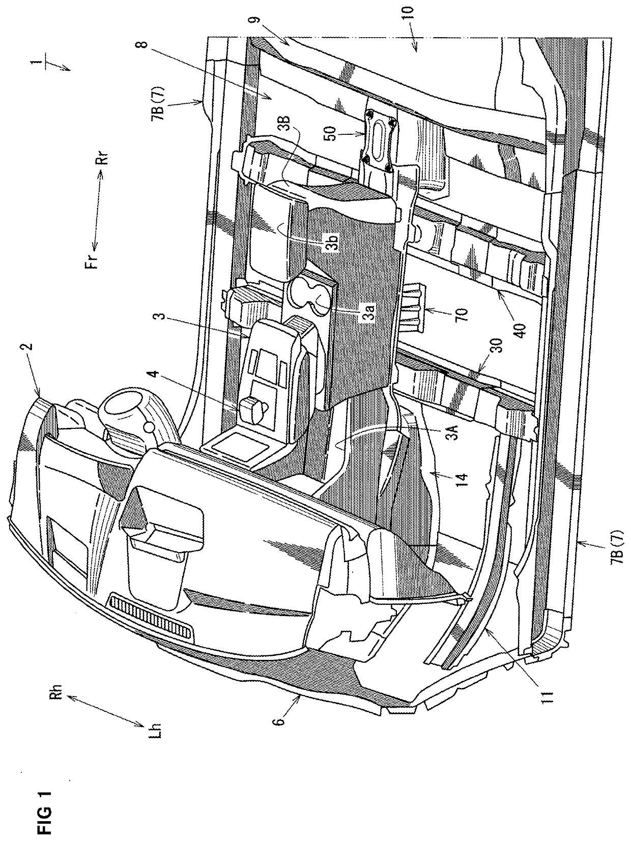
[0085]A vehicle in this embodiment is, for example, an electric vehicle that includes a battery unit such as a lithium ion secondary battery, and a rotary electric machine rotated by power supplied from the battery unit, and uses output from the rotary electric machine as a drive force. With reference to FIGS. 1 to 15, a lower vehicle-body structure in a vehicle interior part of such an electric vehicle 1 will be described in detail.

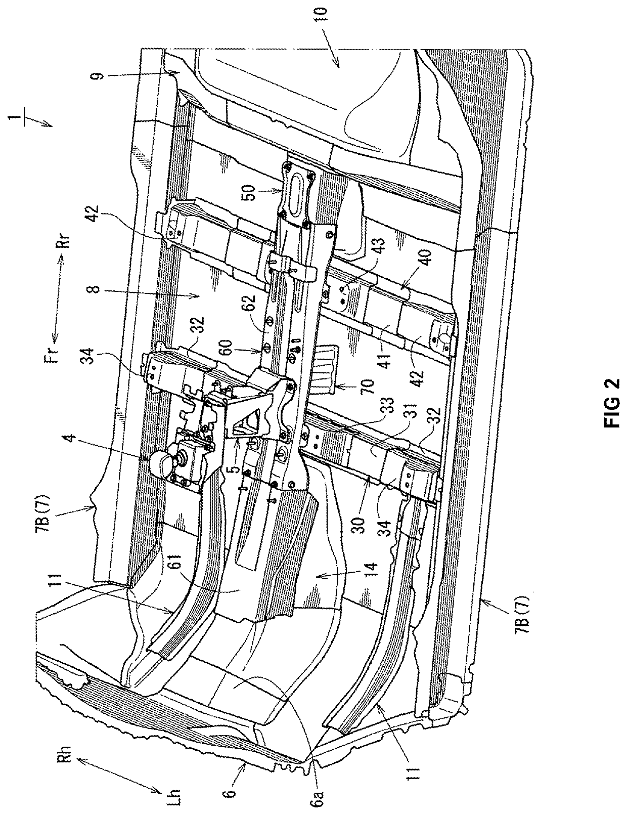
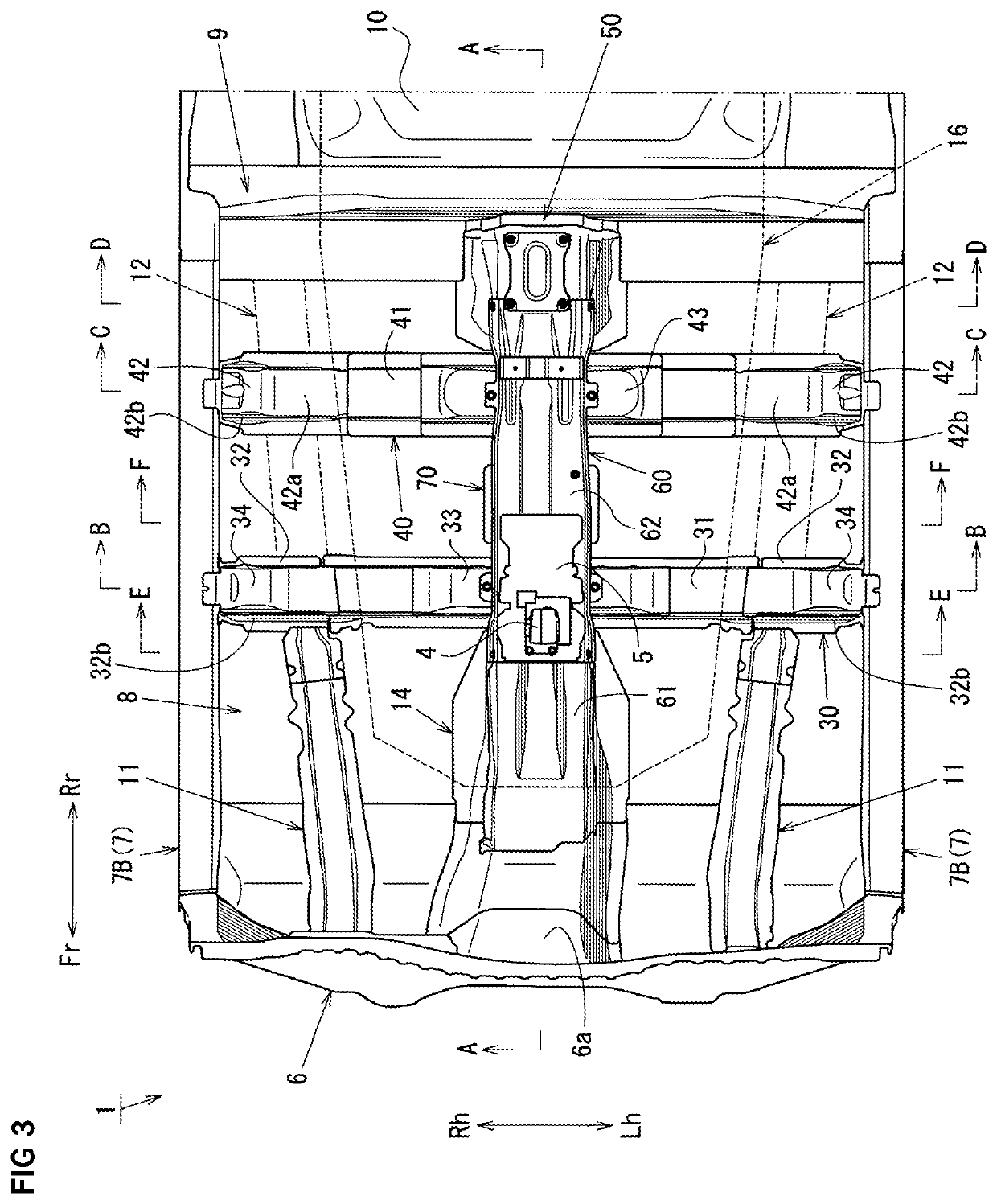
[0086]FIG. 1 is a perspective view of an appearance of a vehicle interior part of the electric vehicle 1, FIG. 2 is a perspective view of an appearance of a lower vehicle body of the electric vehicle 1, FIG. 3 is a plan view of the lower vehicle body, FIG. 4 is a sectional view taken in the direction of arrow A-A in FIG. 3, and FIG. 5 is a perspective view of an appearance of an expanding member 14 viewed from a vehicle rear side.

[0087...

second embodiment

The Second Embodiment

[0240]An increase in resistance to lateral collision, and also a reduction in weight of a console support bracket and an increase in support rigidity of the console support bracket, is achieved by a lower vehicle-body structure of an electric vehicle including a floor panel that forms a vehicle cabin floor; a floor cross member disposed below a front part of a front seat to linearly extend in a vehicle width direction between a pair of left and right side sills at a height of the side sills above the floor panel; and a console support bracket that is disposed above a middle of the floor cross member and supports a console. An upper enlarged section with a section enlarged upward to a height of the console support bracket is provided on a middle upper part of the floor cross member.

[0241]Now, with reference to the drawings, an embodiment of the present disclosure will be described. The drawings show a lower vehicle-body structure of an electric vehicle, FIG. 1 is...


PUM


Abstract

A lower vehicle-body structure of the electric vehicle includes a pair of left and right side sills; a substantially flat front floor panel; a first floor cross member disposed on an upper surface of the front floor panel located below a front part of a front seat; a second floor cross member disposed on an upper surface of the front floor panel 8 located below a rear part of the front seat; a kick-up portion raised from a rear end of the front floor panel 8 toward a vehicle upper side; and a console support bracket that has a front part connected to a vehicle body on a vehicle front side and a rear part connected to the kick-up portion. A lower part of the console support bracket is secured to the first and second floor cross members.

Description

BACKGROUNDTechnical Field[0001]The present disclosure relates to a lower vehicle-body structure of an electric vehicle, for example, including no exhaust pipe on a vehicle lower side of a floor panel.Background Art[0002]Recently, there has been a growth in the use of electric vehicles that use output from a rotary electric machine as a drive force, instead of an internal combustion engine using gasoline or the like as fuel. In such an electric vehicle, an on-vehicle battery that supplies power to the rotary electric machine is disposed, for example, on a vehicle lower side of a floor panel that forms a vehicle interior floor surface, as described, for example, in International Publication No. WO2012 / 063393 and Japanese Patent Laid-Open No. 2013-147137.[0003]International Publication No. WO2012 / 063393 discloses a vehicle-body structure in which a floor cross member disposed on an upper surface of a floor panel and connecting left and right side sills in a vehicle-width direction is d...

Claims


Application Information

Patent Timeline
IPC IPC(8): B62D21/04B62D25/20B62D27/02B62D21/09B60R7/06
CPCB62D21/09B60R7/06B62D21/04B60R2011/0007B62D25/2036B62D27/023B62D25/20B62D25/2018B60K1/04
Inventor MATSUDA, YAMATONAKAYAMA, NOBUYUKIYAMADA, MORIHIDEKOUNO, KATSUHITOTAKEBAYASHI, TOSHIHIRO
Owner MAZDA MOTOR CORP
Why Eureka
Try Eureka