Optical imaging apparatus

a technology of optical imaging and apparatus, applied in the field of optical imaging apparatus, can solve the problems of inconvenient use in many different locations, and achieve the effects of preventing unnecessary weight increase, suppressing the height of the apparatus, and improving the stability

Inactive Publication Date: 2014-06-12
SHIMADZU CORP +1
View PDF17 Cites 15 Cited by
  • Summary
  • Abstract
  • Description
  • Claims
  • Application Information

AI Technical Summary

Benefits of technology

[0037]In accordance with the optical imaging apparatus according to the present invention, both the measuring light projected onto the biological sample and the emitted light obtained from the biological sample are bent by the common reflection optical unit. Thus, even in a configuration in which the measuring light is projected onto the biological sample from immediately above or below the biological sample, that is, along an axis extending in a vertical direction, and the emitted light is obtained from the biological sample along the same axis, various optical components and elements included in the illuminating unit or the imaging unit can be arranged not in the vertical direction, but in a horizontal direction. Accordingly, the height of the apparatus can be suppressed, and the entire apparatus can be made compact. Suppressing the height of the apparatus also improves its stability and prevents an unnecessary increase in its weight. Thus, a weight reduction of the apparatus can also be achieved.
[0038]The optical imaging apparatus according to the present invention can particularly be configured so that the measuring light is projected from below and the emitted light directed downward is observed. In this case, when the biological sample is a small animal such as a mouse or a rat, its abdominal side can be observed in a natural body position with its abdomen oriented downward, not facing upward in an unnatural body position. Accordingly, an excessive burden on the small animal can be avoided, which improves the reliability of the measurement.

Problems solved by technology

Such an apparatus is also inconvenient for use in many different locations.

Method used


Image

  • Optical imaging apparatus
  • Optical imaging apparatus
  • Optical imaging apparatus

Examples


Embodiment Construction

[0045]Hereinafter, an optical imaging apparatus according to one embodiment of the present invention is described with reference to the attached drawings.

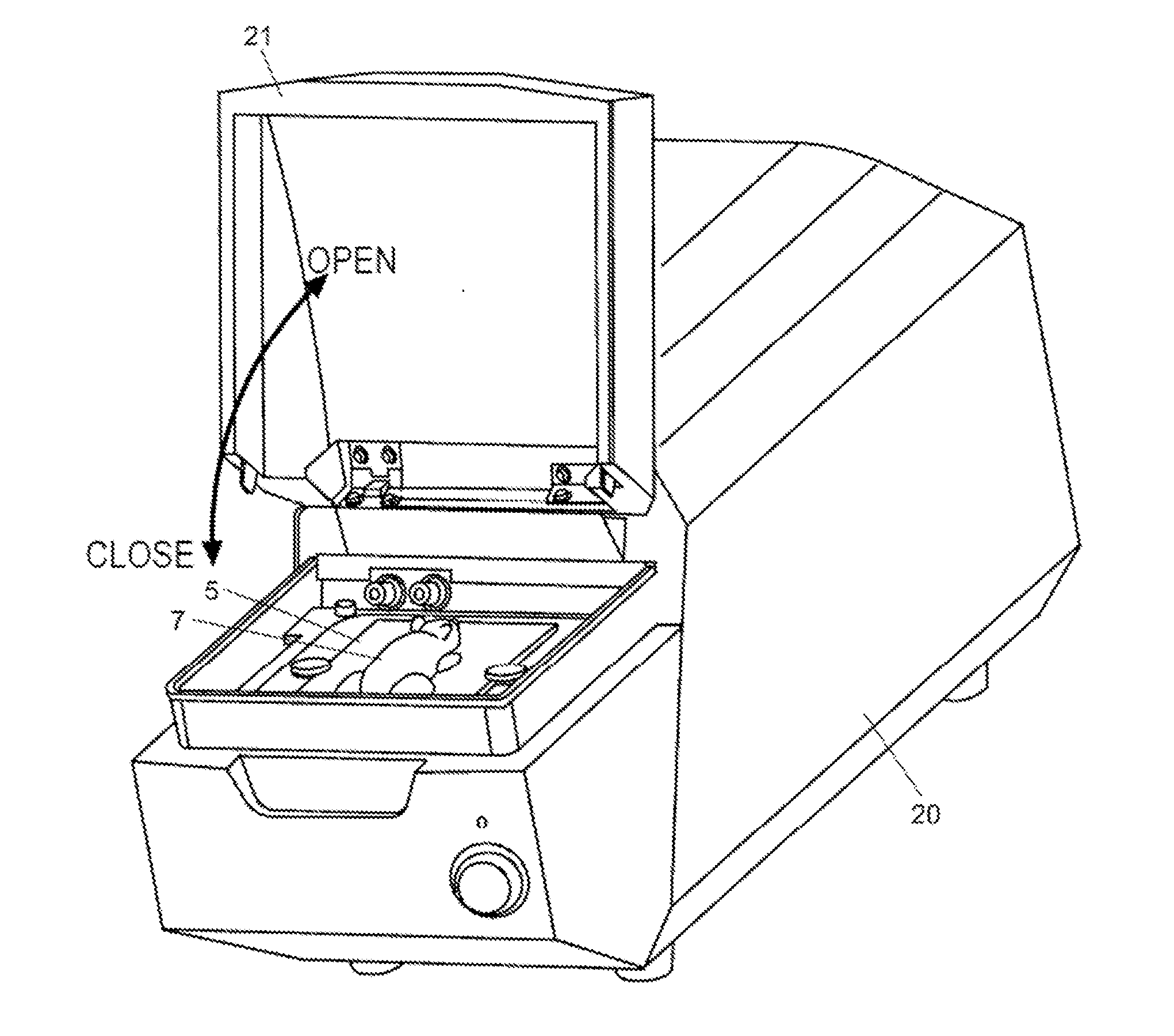
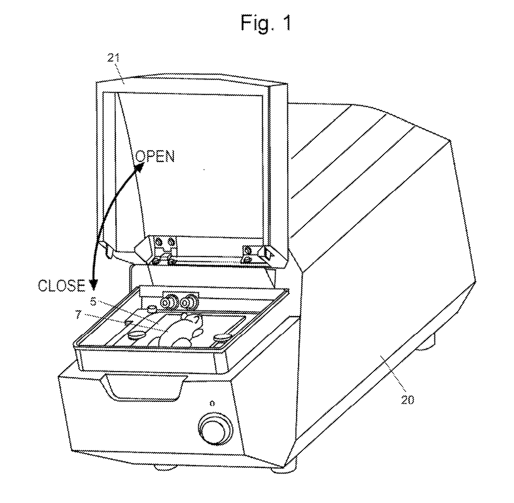
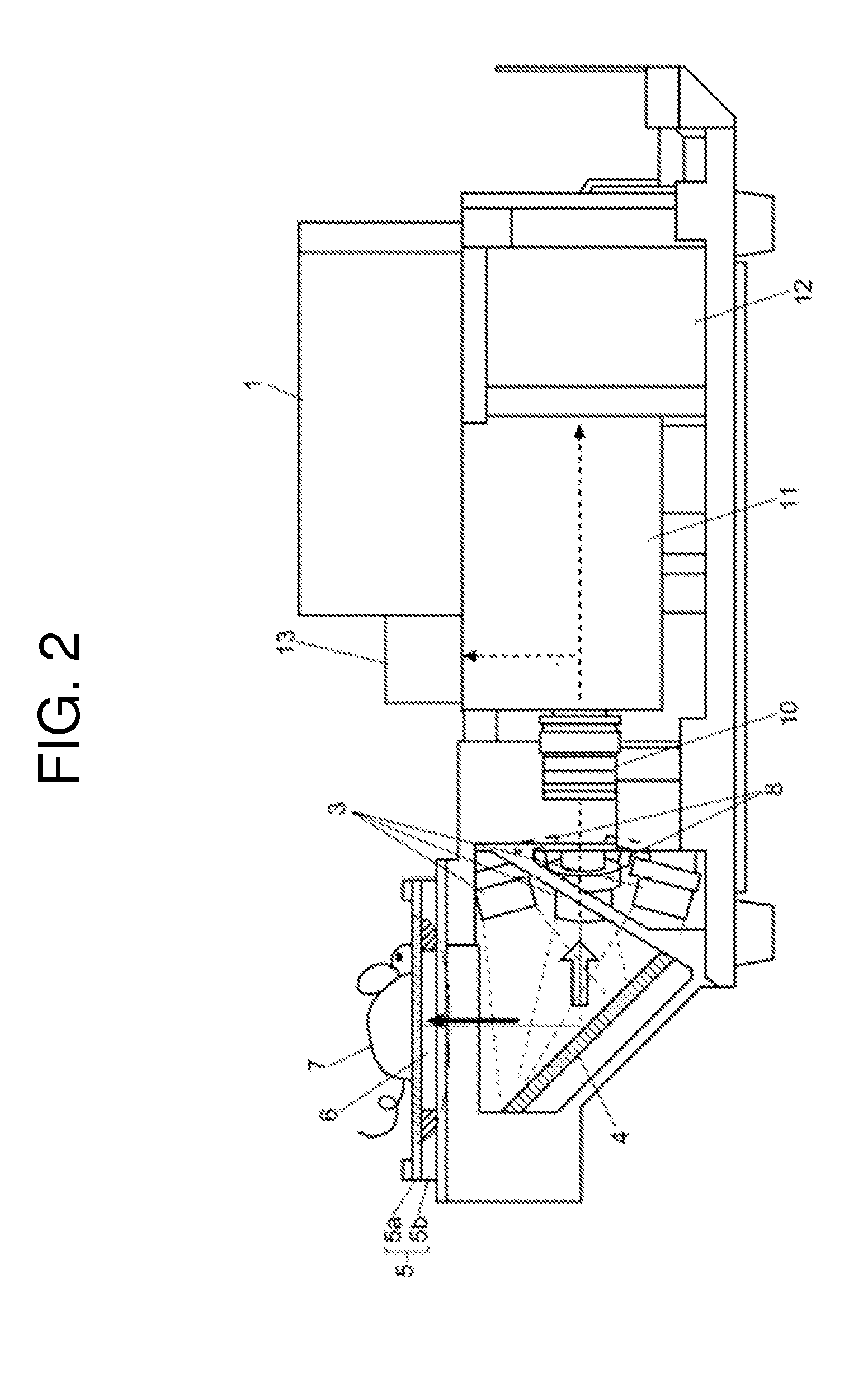
[0046]FIG. 1 is an external perspective view of an optical imaging apparatus according to one embodiment of the present invention, with a sample mounting upper lid being opened. FIG. 2 is a partially-broken schematic side view of the optical imaging apparatus according to the present embodiment, with an outer housing removed. FIG. 3 is a configuration diagram of an optical system in the optical imaging apparatus according to the present embodiment. That is, FIG. 2 illustrates the spatial arrangement of the components and elements of the optical system in the optical imaging apparatus according to the present embodiment, and FIG. 3 illustrates the functional configuration of the optical system.

[0047]As shown in FIG. 1, the optical imaging apparatus according to the present embodiment has a substantially box-like shape longer in the ...


PUM


Abstract

Measuring light emitted from a laser light source and split into four light rays through optical fibers is emitted into a space from emission units, and bent upward at a mirror. The measuring light passes through a window in the center of the sample stage and strikes a lower surface of the biological sample placed on the sample stage. A portion of fluorescence emitted through excitation by the measuring light passes through the window, is bent in an opposite direction from the measuring light by the mirror, and guided to a fluorescence camera. An objective lens, and a spectroscopic unit for separating visible wavelength components are horizontally arranged between the camera and the mirror. Although the projection of the measuring light and the detection of the fluorescence are performed perpendicularly to the biological sample, the optical components and elements are horizontally arranged.

Description

TECHNICAL FIELD[0001]The present invention relates to an optical imaging apparatus which projects light onto a biological sample, and two-dimensionally detects various types of light such as transmitted light, reflected light, and fluorescence obtained from the sample in response to the projected light to thereby acquire an image showing the optical properties or characteristics of the sample.BACKGROUND ART[0002]When excitation light emitted from a light source (such as a halogen lamp or a semiconductor laser) is projected onto a small animal (such as a mouse or a rat) to which a fluorescent-labeled probe has been administered, fluorescence is emitted from the portion where the fluorescent-labeled probe is accumulated, such as an organ. The fluorescence is detected by a highly-sensitive camera, and an image of its intensity distribution is created. Accordingly, a distribution or a behavior of a target molecular species in the small animal in vivo can be non-invasively investigated. ...

Claims


Application Information

Patent Timeline
Patent Type & Authority Applications(United States)
IPC IPC(8): A61B5/00
CPCG01N21/6456A61B5/0071F04C2270/041G02B17/023A61B2560/0431A61B2503/40
Inventor SASAYAMA, TOMOKIYAMAMOTO, SATOSHISOGA, KOHEI
Owner SHIMADZU CORP
Why Eureka
Try Eureka