Method for isolating a cabin wall of an aircraft or for cooling or heating of cabin air and a cabin wall suitable therefore

a technology for cabin walls and aircraft, which is applied in the direction of fuselages, transportation and packaging, and energy-saving board measures, etc. it can solve the problems of occupying considerable space in the aircraft, and reducing the insulation effect, so as to increase the humidity of the air within the aircraft cabin, the effect of increasing the weight of the aircra

Active Publication Date: 2012-04-17
AIRBUS OPERATIONS GMBH
View PDF3 Cites 13 Cited by
  • Summary
  • Abstract
  • Description
  • Claims
  • Application Information

AI Technical Summary

Benefits of technology

[0004]The temperature of the air in the aircraft cabin, the aircraft cabin air, should be within a range that is convenient to passengers. Passengers themselves contribute to the heating of the cabin air over time. For this reason cooling of the cabin air is required in order to ensure constant travel comfort. Cooling of the aircraft cabin air normally takes place with the use of cold fresh air. The cold fresh air is mixed, in a mixing chamber, with the already present aircraft cabin air, as a result of which mixing the temperature of the mixture is reduced compared to that of the original aircraft cabin air and kept constant over time respectively. The mixing chamber and its inlet and outlet lines result in an increase in weight and furthermore take up considerable space within the aircraft.
[0010]This active insulation of an aircraft cabin results in that the dimensioning of the insulation requires a smaller installed volume. In this way it is either possible to reduce the external diameter of the aircraft fuselage and thus the aircraft's drag in flight. Or it is possible to enlarge the aircraft cabin interior, as a result of which passenger comfort is enhanced, and more passengers can be accommodated respectively.
[0011]In order to cool the aircraft cabin air the aircraft cabin air is mixed with fresh air in a mixing chamber. As a result of cooling, according to the invention, of the aircraft cabin air, the temperature of the fresh air can be selected so as to be higher so that the energy requirement for conditioning the fresh air can be reduced, which results in lower operating costs.
[0016]It is particularly advantageous if between these two layers of insulation the spacing remains the same, so that turbulences of the flowing aircraft cabin air can be avoided.
[0018]The aircraft cabin air is cooled within the aircraft cabin wall, as a result of which water can condense. Over time this water can accumulate in the aircraft cabin wall and can result in an increase of weight of the aircraft and in a reduction of insulation effect. The drained condensation water can either be collected and removed from the aircraft in a targeted manner, or it can be used again for enriching aircraft cabin air in order to increase the humidity of the air within the aircraft cabin, thus ensuring thermal comfort. The drainage system thus prevents the above-described increase of weight of the aircraft. Furthermore, as a result of the removal of the condensation water the insulation function of the aircraft cabin wall is ensured even over an extended service life, and corrosion damages are prevented.

Problems solved by technology

The mixing chamber and its inlet and outlet lines result in an increase in weight and furthermore take up considerable space within the aircraft.

Method used


Image

  • Method for isolating a cabin wall of an aircraft or for cooling or heating of cabin air and a cabin wall suitable therefore
  • Method for isolating a cabin wall of an aircraft or for cooling or heating of cabin air and a cabin wall suitable therefore
  • Method for isolating a cabin wall of an aircraft or for cooling or heating of cabin air and a cabin wall suitable therefore

Examples


Embodiment Construction

[0023]In the following drawings the same reference characters are used for identical or similar elements.

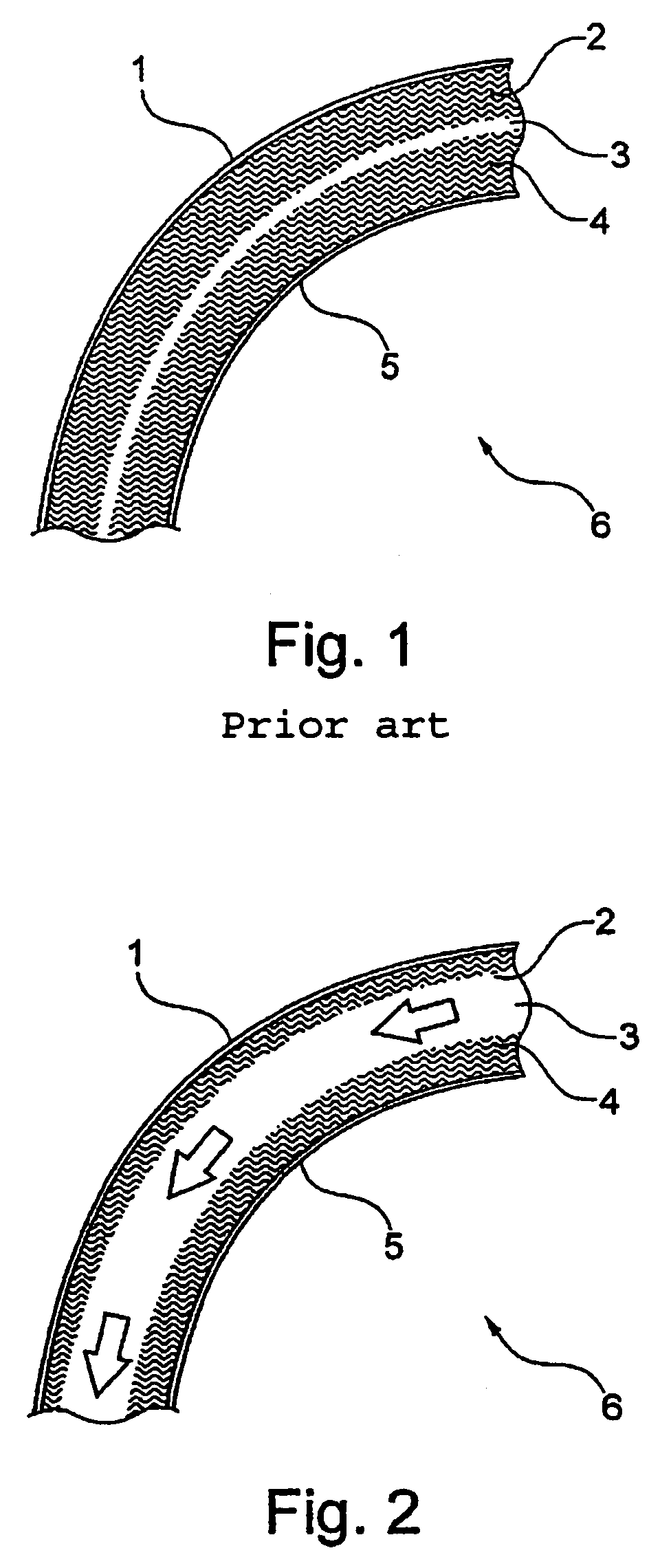
[0024]FIG. 1 shows a diagrammatic cross-section of a part of an aircraft cabin wall according to the state of the art. In this arrangement, the aircraft cabin wall 6 comprises an outer skin 1 and a sidewall panel 5. In this arrangement the insulation is provided by two materials 2 and 4 that have been applied, wherein material 2 is arranged on the outer skin 1, and material 4 is arranged on the sidewall panel 5. In this arrangement the materials 2 and 4 have low thermal conductivity. The arrangement of the insulating materials 2 and 4 can result in a gap 3. This gap varies as a result of production-related factors, or it can be absent altogether. The insulating materials 2 and 4 have to be designed such that they ensure a correspondingly good insulation between the interior region of the aircraft and the exterior region even in the worst case, in other words under the worst condi...


PUM


Abstract

The present invention relates to a method for insulating an aircraft cabin 6 and for the cooling or heating of cabin air in an aircraft, respectively with the method comprising the steps of: introducing aircraft cabin air into an aircraft cabin wall 6; guiding this aircraft cabin air along a section of this aircraft cabin wall 6; and leading this aircraft cabin air away from the aircraft cabin wall 6.

Description

CROSS REFERENCE TO RELATED APPLICATION[0001]This application claims the benefit of the filing date of U.S. Provisional Patent Application No. 61 / 008,790 filed Dec. 21, 2007, the disclosure of which applications is hereby incorporated herein by reference.BACKGROUND OF THE INVENTION[0002]The present invention relates to a method for the cooling or heating of aircraft cabin air, or to an aircraft cabin wall comprising an outer skin and a sidewall panel that is suitable for this method.SUMMARY OF THE INVENTION[0003]An aircraft cabin wall usually comprises an outer skin and a sidewall panel. In this arrangement the sidewall panel is the inner delimitation to the cabin interior. The cabin interior must be insulated by the aircraft cabin wall, in particular against cooling. In this arrangement, insulation is achieved in that insulating material is affixed between the outer skin and the sidewall panel. Usually, primary insulation is arranged on the outer skin, while a second insulation, the...

Claims


Application Information

Patent Timeline
Patent Type & Authority Patents(United States)
IPC IPC(8): B64C1/00
CPCB64C1/066B64C1/40B64D13/08B64D2013/0662B64D2013/0688Y02T50/56Y02T50/50
Inventor DITTMAR, JANHOELLING, MARCMUELLER, RAINER
Owner AIRBUS OPERATIONS GMBH
Why Eureka
Try Eureka