Projector spatially modulating incident light to display images of different colors

a projector and incident light technology, applied in the field of projectors, can solve the problems of increasing costs, occupying considerable space, and complicating miniaturization, and achieve the effects of reducing luminance, increasing green light, and increasing red light luminan

Active Publication Date: 2016-02-16
NEC CORP
View PDF12 Cites 0 Cited by
  • Summary
  • Abstract
  • Description
  • Claims
  • Application Information

AI Technical Summary

Benefits of technology

[0030]Although higher luminance can be achieved in the light source device described in Patent Document 1, the light path must be switched by the rotation means, and this factor leads to increased costs due to the necessity to detect the orientation of the reflection surface during rotation and synchronize the timing of the rotational action of the reflection surface and the timing of lighting of the LED as well as the need for a design that takes into consideration the durability of the drive unit of the rotation means. In addition, a concern also arises regarding the anti-shock property of this configuration. Still further, a configuration, in which a plurality of solid-state light-emitting devices are arranged in ring form and a mechanical construction, such as rotation means, carries out switching of the light path, takes up considerable space and complicates miniaturization.
[0032]Although the luminance of the green light is increased in the display device described in Patent Document 2, the output of the red solid-state light source is limited and the luminance of the red light thus reduced, and as a result, the output of the blue solid-state light source is limited taking as a reference the red light for which luminance has been reduced. In the current state, blue LEDs have the greatest margin in the light output while achieving color balance, and as a result, if the red and blue LEDs are exchanged in the configuration described in Patent Document 2, the output of green can be increased while maintaining the output of red. However, when the output of two colors is less than that of one color, for example, if the output of both red and green is less than that of blue as in the current state of LEDs, the output of one of the two colors will become a bottleneck and the effect of increasing the output of the display device will be diminished.
[0033]Still further, in this configuration, a state in which the three colors, red, green, and blue, are emitted and a state in which only the two colors red and green are emitted are repeatedly switched. If this switching is not carried out at a sufficiently short periods, i.e., at a high frequency, the picture quality will be impaired due to a phenomenon similar to “color breaking (rainbow noise)” in a single-panel DLP projector. Accordingly, high-speed switching at a minimum of 60 times per second and more preferably two times or four times this speed is required. However, in order to increase the switching frequency, the operating frequency of the circuit that drives the LEDs or the display device must be increased. Typically, the power consumption increases in proportion of the increase of the operating frequency of this type of circuit. As a result, the power consumption of the projector is increased.
[0034]It is therefore an exemplary object of the present invention to provide a projector that offers a combination of features that includes small size, high luminance, low cost and high picture quality and that allows reducing to a required minimum limitation imposed on the output of a solid-state light source without requiring mechanical switching of the light path by means such as rotation means.

Problems solved by technology

Although higher luminance can be achieved in the light source device described in Patent Document 1, the light path must be switched by the rotation means, and this factor leads to increased costs due to the necessity to detect the orientation of the reflection surface during rotation and synchronize the timing of the rotational action of the reflection surface and the timing of lighting of the LED as well as the need for a design that takes into consideration the durability of the drive unit of the rotation means.
Still further, a configuration, in which a plurality of solid-state light-emitting devices are arranged in ring form and a mechanical construction, such as rotation means, carries out switching of the light path, takes up considerable space and complicates miniaturization.
Although the luminance of the green light is increased in the display device described in Patent Document 2, the output of the red solid-state light source is limited and the luminance of the red light thus reduced, and as a result, the output of the blue solid-state light source is limited taking as a reference the red light for which luminance has been reduced.
However, when the output of two colors is less than that of one color, for example, if the output of both red and green is less than that of blue as in the current state of LEDs, the output of one of the two colors will become a bottleneck and the effect of increasing the output of the display device will be diminished.
If this switching is not carried out at a sufficiently short periods, i.e., at a high frequency, the picture quality will be impaired due to a phenomenon similar to “color breaking (rainbow noise)” in a single-panel DLP projector.
Typically, the power consumption increases in proportion of the increase of the operating frequency of this type of circuit.
As a result, the power consumption of the projector is increased.

Method used


Image

  • Projector spatially modulating incident light to display images of different colors
  • Projector spatially modulating incident light to display images of different colors
  • Projector spatially modulating incident light to display images of different colors

Examples


Embodiment Construction

[0050]Exemplary embodiments of the present invention are next described with reference to the accompanying drawings.

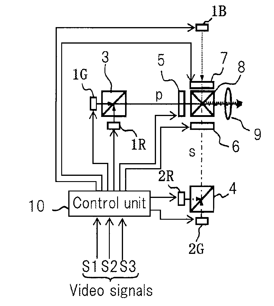
[0051]FIG. 1 is a block diagram showing the configuration of the projector that is an exemplary embodiment of the present invention.

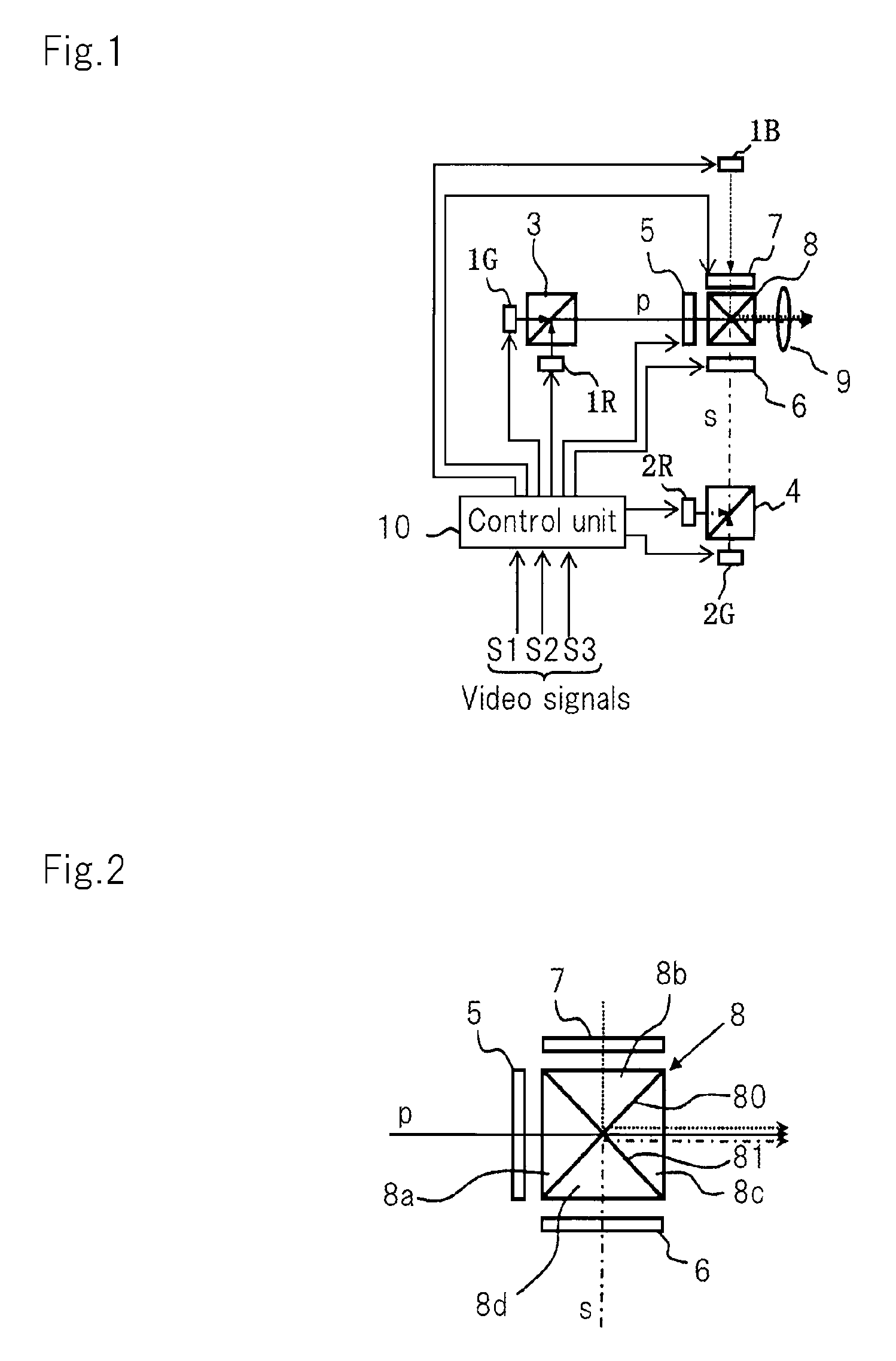
[0052]The projector shown in FIG. 1 includes: solid-state light sources 1B, 1G, 1R, 2G, and 2R; dichroic prisms 3 and 4; display elements 5-7; polarization cross dichroic prism 8; projection optics 9; and control unit 10.

[0053]Solid-state light source 1B is a solid-state light source having a peak wavelength in the blue wavelength band and is constituted by, for example, an LED or semiconductor laser for which the color of emitted light is blue. In the present exemplary embodiment, solid-state light source 1B emits blue P-polarized light or blue S-polarized light.

[0054]Solid-state light sources 1G and 2G are solid-state light sources having peak wavelength in the green wavelength band and are constituted by, for example, LEDs or semiconduc...


PUM


Abstract

Green and red light from first green and red light sources light a first element. Green and red light from second green and red light sources light a second element. Blue light from a blue light source light a third element. A control unit causes an image of a first video signal to be displayed on the first element during lighting of first red source, and causes an image of a second video signal to be displayed on the first element during lighting of the first green source. The unit causes an image of the first signal to be displayed on the second element during lighting of the second red source, and causes an image of the second signal to be displayed on the second element during lighting of the second green source. The unit causes an image of a third video signal to be displayed on the third element.

Description

[0001]This application is a National Stage Entry of PCT / JP2012 / 058141 filed Mar. 28, 2012, which claims priority from Japanese Patent Application 2011-099814 filed Apr. 27, 2011, the contents of all of which are incorporated herein by reference, in their entirety.TECHNICAL FIELD[0002]The present invention relates to a projector, and more particularly relates to a projector that is provided with a solid-state light source, which is epitomized by an LED (Light-Emitting Diode).BACKGROUND ART[0003]Among recent projectors, some projectors are provided with LEDs of three colors, red, green and blue. They use display elements such as liquid crystal panels to spatially modulate light from the LEDs for each color to generate image light of each color, and that then project a color image made up by this image light.[0004]Typically, the output characteristics differ for each of the red LED, green LED, and blue LED, the maximum output value of the red LED and green LED being smaller than that o...

Claims


Application Information

Patent Timeline
Patent Type & Authority Patents(United States)
IPC IPC(8): G03B21/00H04N9/31G03B33/12G09G5/02G03B21/28G03B21/20H05B33/08H05B44/00
CPCG09G5/02G03B21/2033G03B33/12H04N9/3105H04N9/3155H04N9/3164H04N9/3197G03B21/2073G03B21/28H05B33/0845H05B45/10
Inventor SUZUKI, NAOFUMI
Owner NEC CORP
Why Eureka
Try Eureka