

Variable displacement swash plate type compressor
- Summary
- Abstract
- Description
- Claims
- Application Information
AI Technical Summary
Benefits of technology
Problems solved by technology
Method used
Image


Examples
embodiment 1
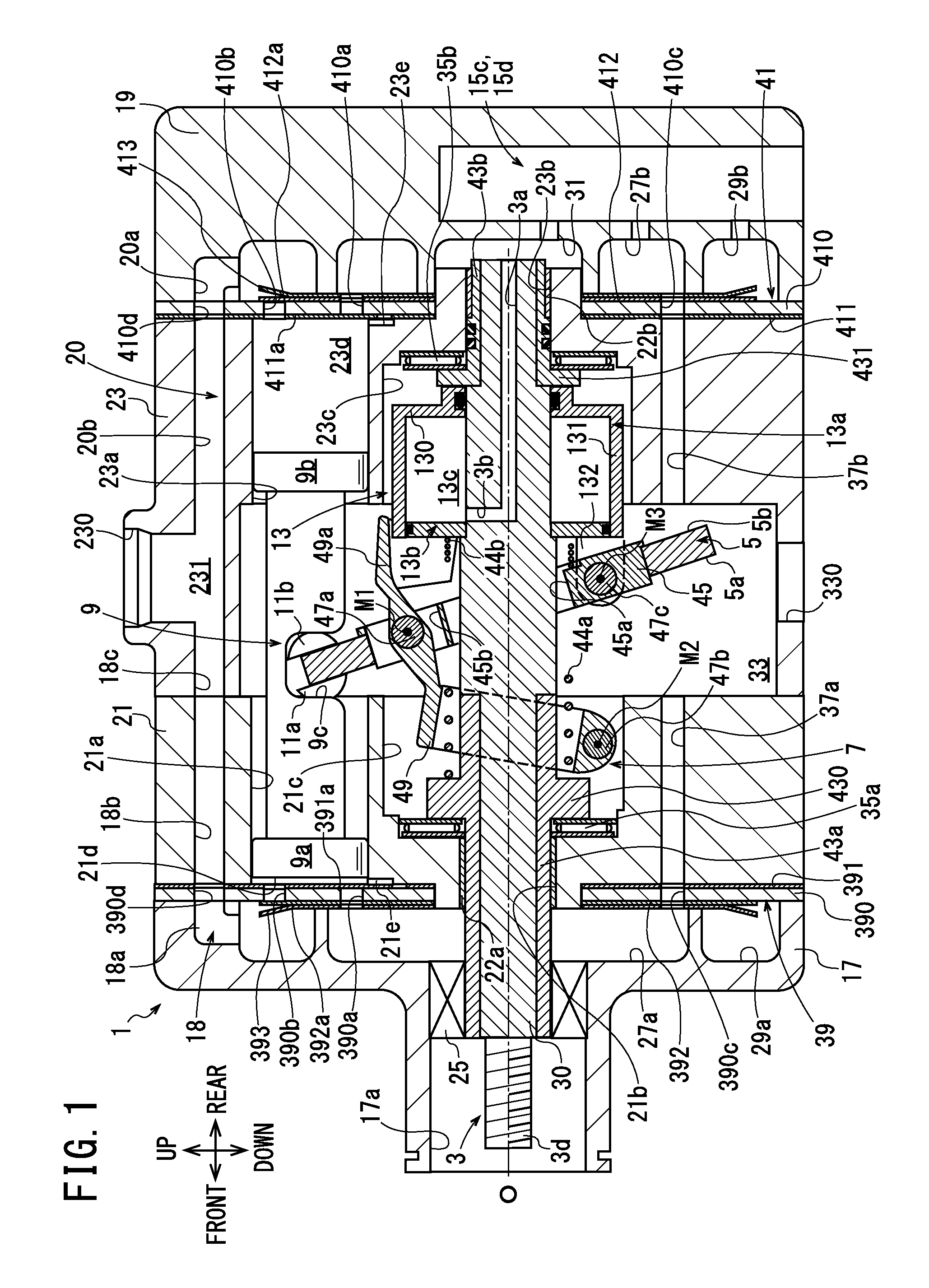
[0029]As shown in FIG. 1, the compressor in embodiment 1 includes a housing 1, a drive shaft 3, a swash plate 5, a link mechanism 7, a plurality of pistons 9, a pair of shoes 11a and 11b, an actuator 13, and a control mechanism 15 shown in FIG. 2.
[0030]As shown in FIG. 1, the housing 1 includes a front housing 17 located in the front of the compressor, a rear housing 19 located in the rear of the compressor, first and second cylinder blocks 21 and 23 located between the front housing 17 and the rear housing 19, and first and second valve forming plates 39 and 41.
[0031]In the front housing 17, a boss 17a projecting forward is formed. A shaft seal device 25 is provided in the boss 17a. In the front housing 17, a first suction chamber 27a and a first discharge chamber 29a are formed. The first suction chamber 27a is located on the inner circumferential side of the front housing 17. The first discharge chamber 29a is formed in an annular shape and is located on the outer circumferential...
embodiment 2
[0112]In a compressor in embodiment 2, a second supporting member 46 shown in FIG. 7 is pressed into the drive shaft main body 30 instead of the second supporting member 43b in the compressor in embodiment 1. Consequently, in the compressor, the drive shaft 3 is configured by the drive shaft main body 30, the first supporting member 43a, and the second supporting member 46.
[0113]In the compressor, a second sliding bearing 22c is provided in the second shaft hole 23b instead of the second sliding bearing 22b. The second sliding bearing 22c is also equivalent to the radial bearing in the present invention. Note that a roller bearing may be provided instead of the second sliding bearing 22c.
[0114]The second supporting member 46 is pressed into the rear end side of the drive shaft main body 30 and located in the second shaft hole 23b. The second supporting member 46 is also equivalent to the cap in the present invention. A flange 461 is formed at the front end of the second supporting ...
embodiment 3
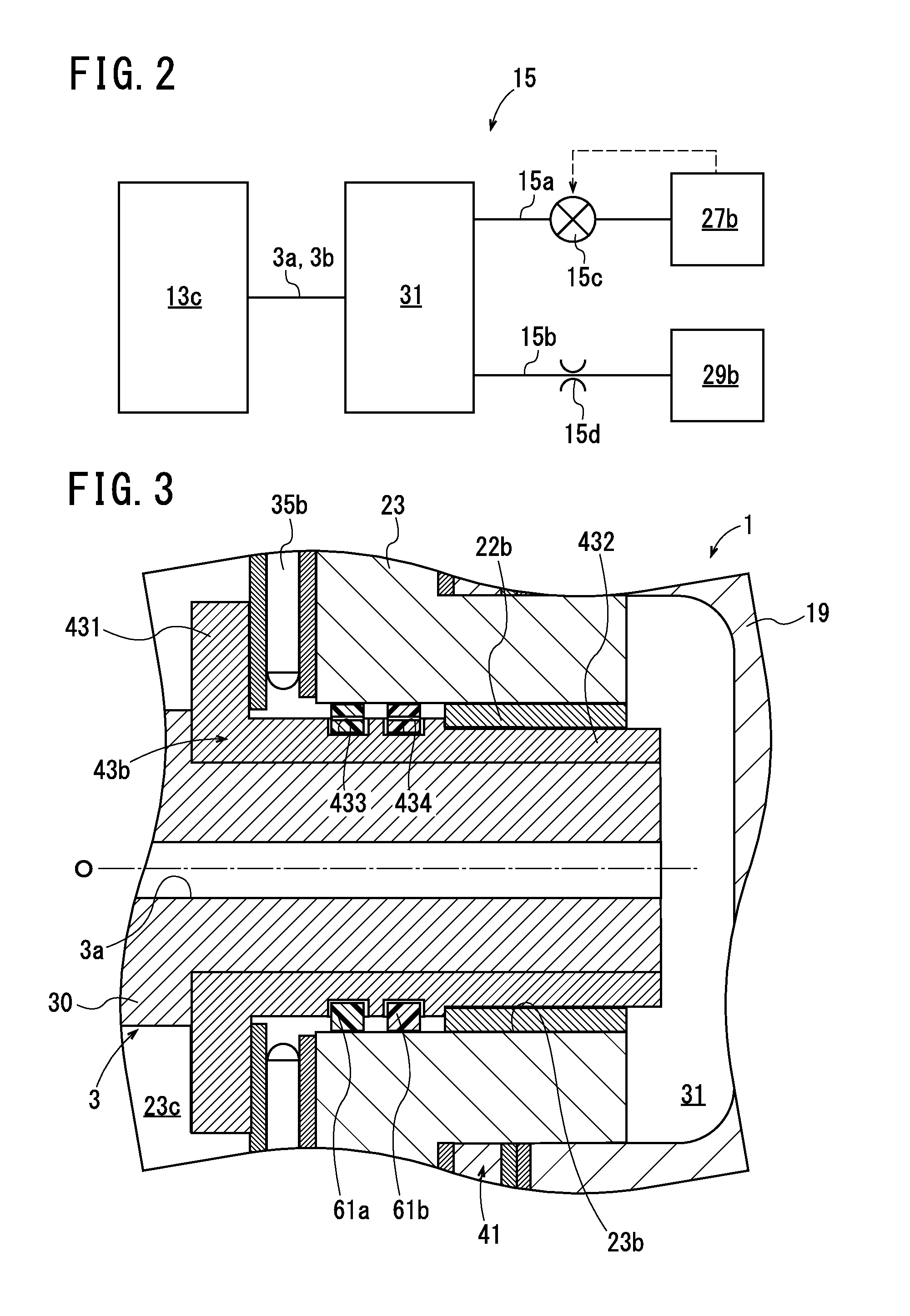
[0119]In a compressor in embodiment 3, first and second annular members 65a and 65b shown in FIG. 8A are adopted instead of the first and second annular members 61a and 61b in the compressor in embodiment 1. The first and second annular members 65a and 65b are also made of PEEK. The first and second annular members 65a and 65b are also respectively accommodated in the first and second recessed strip portions 433 and 434 and located between the second supporting member 43b and the second shaft hole 23b.
[0120]The first and second annular members 65a and 65b have the same configuration and respectively include joint gap 67. The configuration is explained below with reference to the joint gap 67 of the first annular member 65a as an example.
[0121]As shown in FIGS. 8A and 8B, the joint gap 67 is formed by first to third cutouts 670a to 670c and a pair of communication grooves 670d and 670e. The first cutout 670a extends in the axial direction of the first annular member 65a. The second ...
PUM
 Abstract
Description
Claims
Application Information