
Fan assembly and fan hub cap

Inactive Publication Date: 2015-06-18
GE AVIATION SYST LLC
View PDF4 Cites 3 Cited by
  • Summary
  • Abstract
  • Description
  • Claims
  • Application Information

AI Technical Summary

Benefits of technology

The fan assembly has a hub with blades attached to it, and a cap that can be attached to the hub. The cap has slots that fit the blades, which makes them shorter when the cap is attached to the hub. This makes the fan blades work more efficiently.

Problems solved by technology

With any new fan design, costly new production tooling is also needed to then manufacture the fan.

Method used


Image

  • Fan assembly and fan hub cap
  • Fan assembly and fan hub cap
  • Fan assembly and fan hub cap

Examples


Embodiment Construction

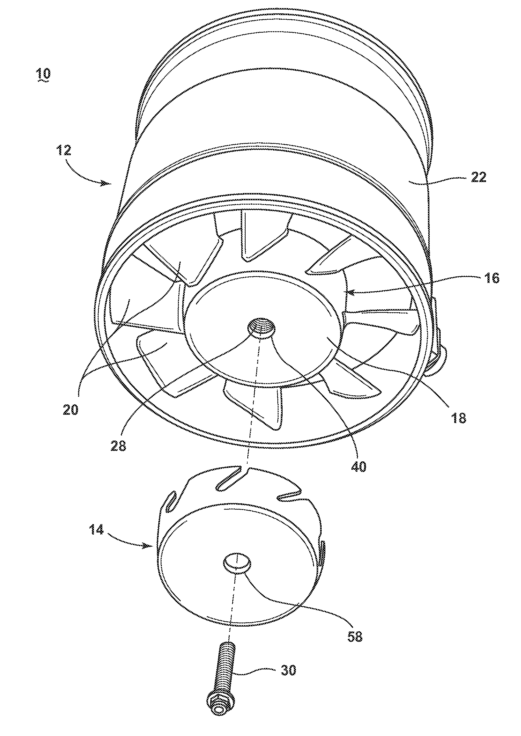
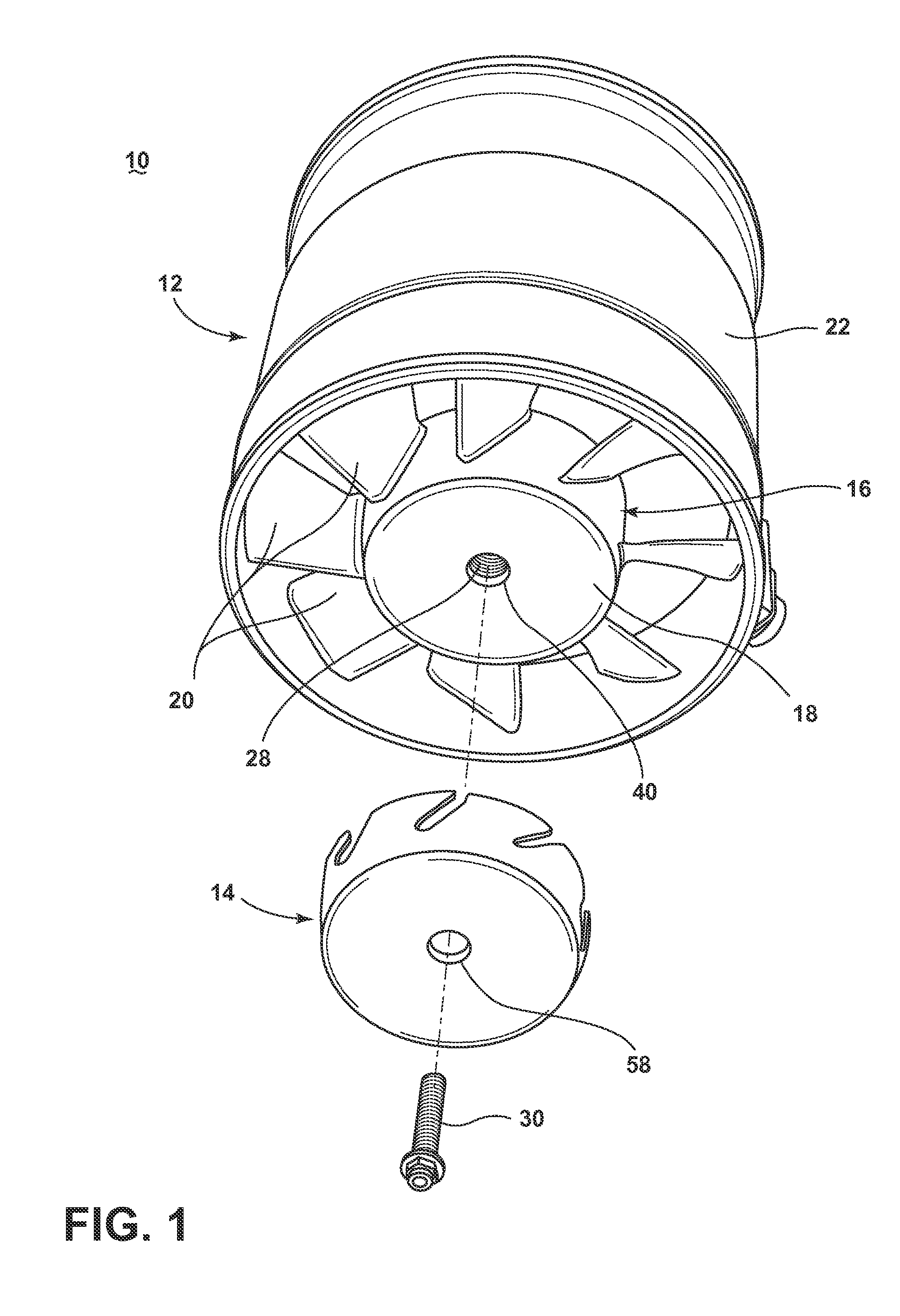
[0012]FIG. 1 is a perspective view of a fan assembly 10. The fan assembly 10 includes a fan 12 and a hub cap 14 configured to selectively mount to the fan 12, as described below. The fan 12 includes an impeller 16 having a hub 18 with a plurality of blades 20 extending radially from the hub 18. The fan 12 further includes a fan housing 22 which receives the impeller 16. The fan 12 is shown herein as an axial fan that increases the pressure of air flowing through it; this fan 12 is illustrated for exemplary purposes only, and the hub cap 14 can be configured for use with a wide variety of fans. The fan assembly 10 can function to create air flow without or without the hub cap 14.

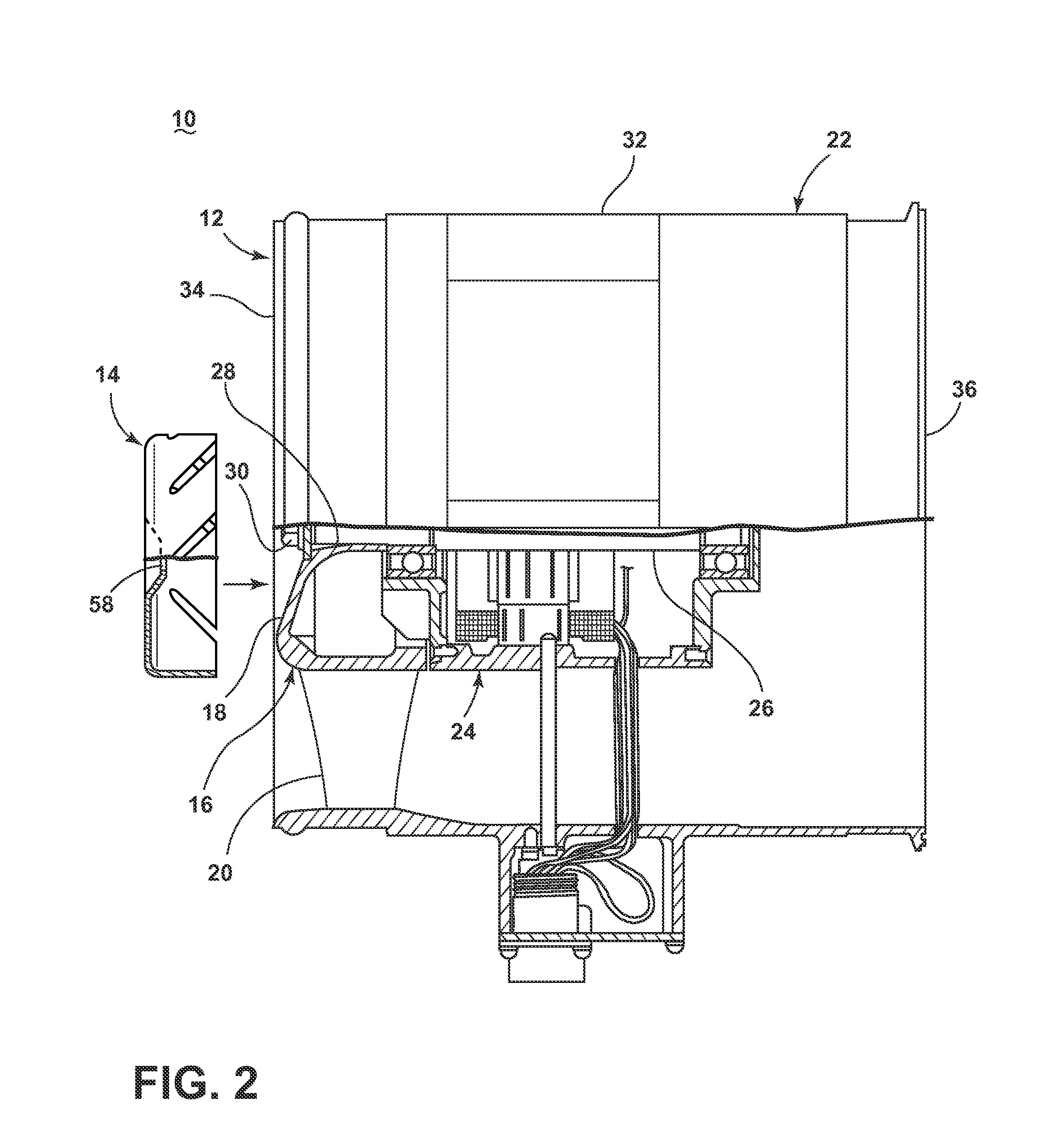
[0013]FIG. 2 is a partial cross-section view of the fan assembly 10 from FIG. 1. The fan assembly 10 further includes a motor 24 coupled to the impeller 16 via an output shaft or drive shaft 26. The hub 18 of the impeller 16 includes a bore 28 through which the drive shaft 26 extends. A fastener 30 couples th...


PUM


Abstract

An apparatus for a fan having an impeller with a hub and a plurality of blades extending from the hub includes a hub cap configured to mount to the hub of the impeller. The hub cap can include a plurality of slots corresponding to the blades of the impeller. The slots are sized to receive the blades when the hub cap is mounted to the hub, which shortens the working length of the blades.

Description

BACKGROUND OF THE INVENTION[0001]Fans used in aviation systems include a case or housing and an impeller contained within the housing to create air flow. A fan is typically designed to meet specific design criteria, which may include alone or in combination any one of at least a particular air flow requirement, pressure rise, and / or rotational speed. When a new design criterion must be met, such as meeting a new air flow requirement, a new fan is designed. An existing fan can be redesigned to meet the new design criteria, such as by altering the impeller size, blade length, number of blades, etc. Often, redesigning the impeller also requires redesigning the fan housing. With any new fan design, costly new production tooling is also needed to then manufacture the fan.BRIEF DESCRIPTION OF THE INVENTION[0002]A fan assembly includes a fan having an impeller comprising a hub with a diameter and plurality of blades extending radially from the hub, with a distance from the hub to a tip of ...

Claims


Application Information

Patent Timeline
IPC IPC(8): F04D29/54
CPCF04D29/541F04D27/002F04D29/329
Inventor KOBAYASHI, SUKEYUKI
Owner GE AVIATION SYST LLC
Learn More