Transmission with an oil pump

a technology of oil pump and transmission line, which is applied in the direction of gearing details, transportation and packaging, gearing, etc., can solve the problems of affecting the operation of the pump, the pump cannot provide any flow at reverse driving, and the relocation of the pump would require a lot of redesign, so as to achieve the effect of flexible arrangement of the oil pump

Inactive Publication Date: 2015-06-18
VOLVO LASTVAGNAR AB
View PDF11 Cites 5 Cited by
  • Summary
  • Abstract
  • Description
  • Claims
  • Application Information

AI Technical Summary

Benefits of technology

[0003]Lubrication of the gears and bearings of the transmission can be facilitated in different ways, by splashing through gearwheels partly submerged in oil or by an oil pump providing a lubrication and cooling flow to bearings and gearwheels distanced from the oil level and not reached by the splashing oil. This flow is normally directed to bearings located high above the oil level and / or not subjected to the splashing flow.
[0004]The oil pump is usually located at a low position in the transmission. Thereby, it will be close to the oil level. That reduces the suction height, which implies a lower risk for cavitation and a more reliable oil flow. Then, it is convenient to drive the pump by the countershaft or by the intermediate gearwheel in a reversing secondary gear set.
[0013]The countershaft rotates in opposite direction when the transmission is in a forward gear speed relative when the transmission is in a backward gear speed. Due to the torque transfer to the oil pump drive shaft over said gearwheel mechanism, the oil pump drive shaft can be driven in one and the same direction independent of the direction of rotation of the countershaft. Further, because said first gearwheel is used in at least one of the forward and backward gear speeds, the oil pump can be driven in all forward and backward speed. By arranging the oil pump in this inventive manner, a minimum of addition gearwheels is needed in order to drive the oil pump in both forward and backward gear speeds. Due to the use of existing gearwheels to drive the oil pump a cost effective arrangement of the oil pump is achieved, whereby the oil pump still can be driven when the transmission is in a reverse gear speed.
[0015]It is further preferred that said first oil pump drive gearwheel is arranged upon the countershaft, such that it can rotate thereupon. The first oil pump drive gearwheel is further connected to the second freewheel, i.e. the input part of the second freewheel is rotationally fixed to the first oil pump drive gearwheel, and the output part of the second freewheel is rotationally fixed to the oil pump drive shaft. The oil pump drive gearwheel is thereby suitably arranged upon a bearing. The arrangement of the oil pump drive gearwheel upon the countershaft, gives the gearwheel a robust arrangement.
[0018]In an alternative embodiment of the invention, the first freewheel is connected to a second pump drive gearwheel, i.e. the input part of the first freewheel is connected to the second pump drive gearwheel. The second pump drive gearwheel meshes with a second gearwheel which is provided upon said countershaft and which is used in at least one of said forward or backward gear speeds. By providing the first freewheel with the second pump drive gearwheel a higher flexibility of the arrangement of the oil pump within the transmission is achieved. The first pump drive gearwheel can thereby be driven by the first gearwheel coaxial with the main shaft and the second pump drive gearwheel can be driven by a second gearwheel which is provided upon the countershaft.
[0019]It is preferred that said first gearwheel which is coaxial with the main shaft and meshes with said first pump drive gearwheel of said second freewheel also meshes with said second gearwheel which is provided upon said countershaft and meshes with said second pump drive gearwheel. The freewheel mechanism can thereby be arranged in a compact manner. The pump can be driven according to the invention both in forward gear speeds and backward gear speeds.

Problems solved by technology

However, in combination with a reversing primary gear set, this will not function properly.
The oil pump would not provide any flow at reverse driving.
A relocation of the pump would require a lot of redesign, and would often not be feasible due to space constraints.
This will be rather costly, though, requiring four additional gearwheels and additional axes of rotation.

Method used


Image

  • Transmission with an oil pump
  • Transmission with an oil pump
  • Transmission with an oil pump

Examples


Embodiment Construction

[0026]In the following only a limited numbers of embodiments of the invention are shown and described, simply by way of illustration of some ways of carrying out the invention.

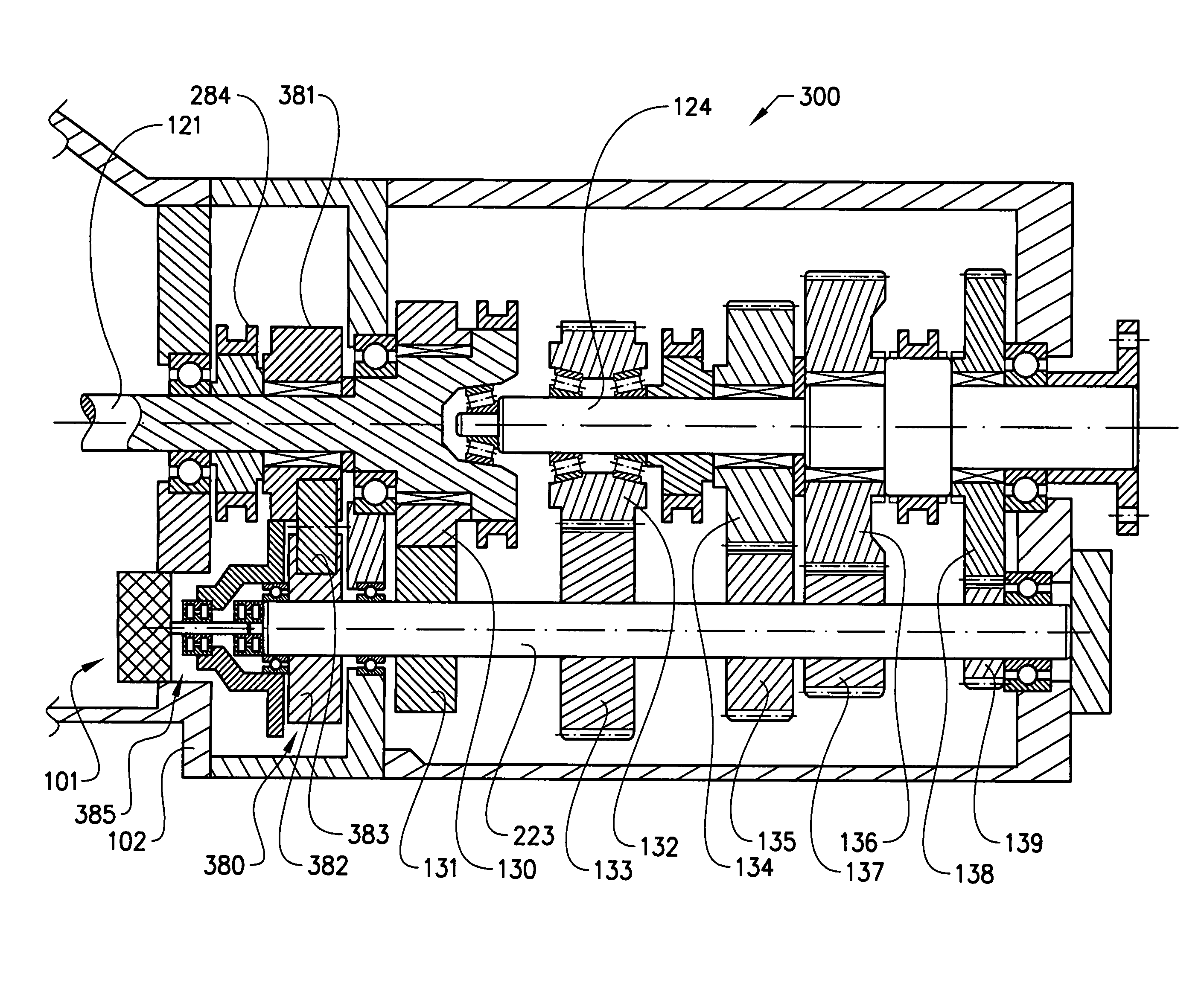
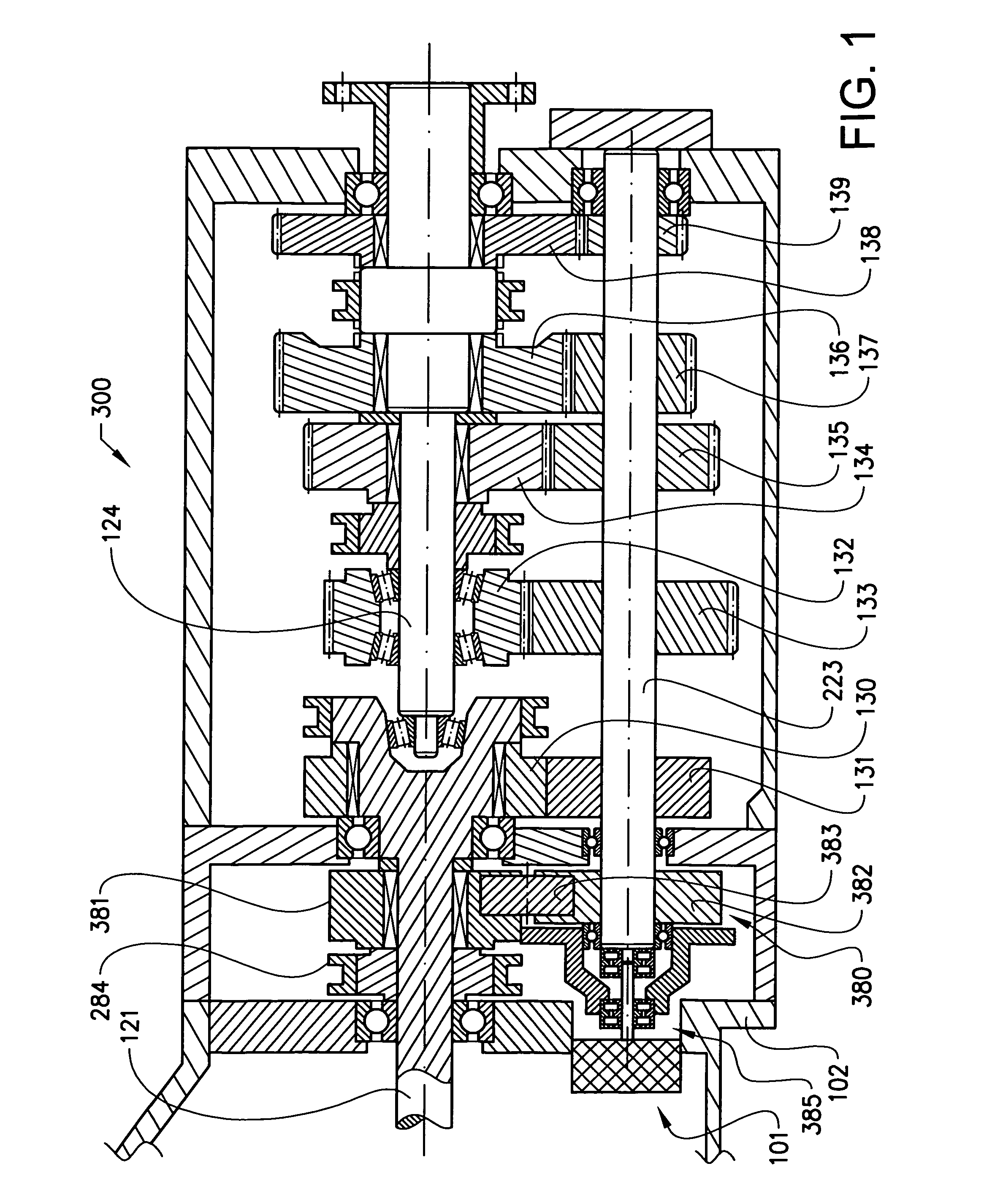
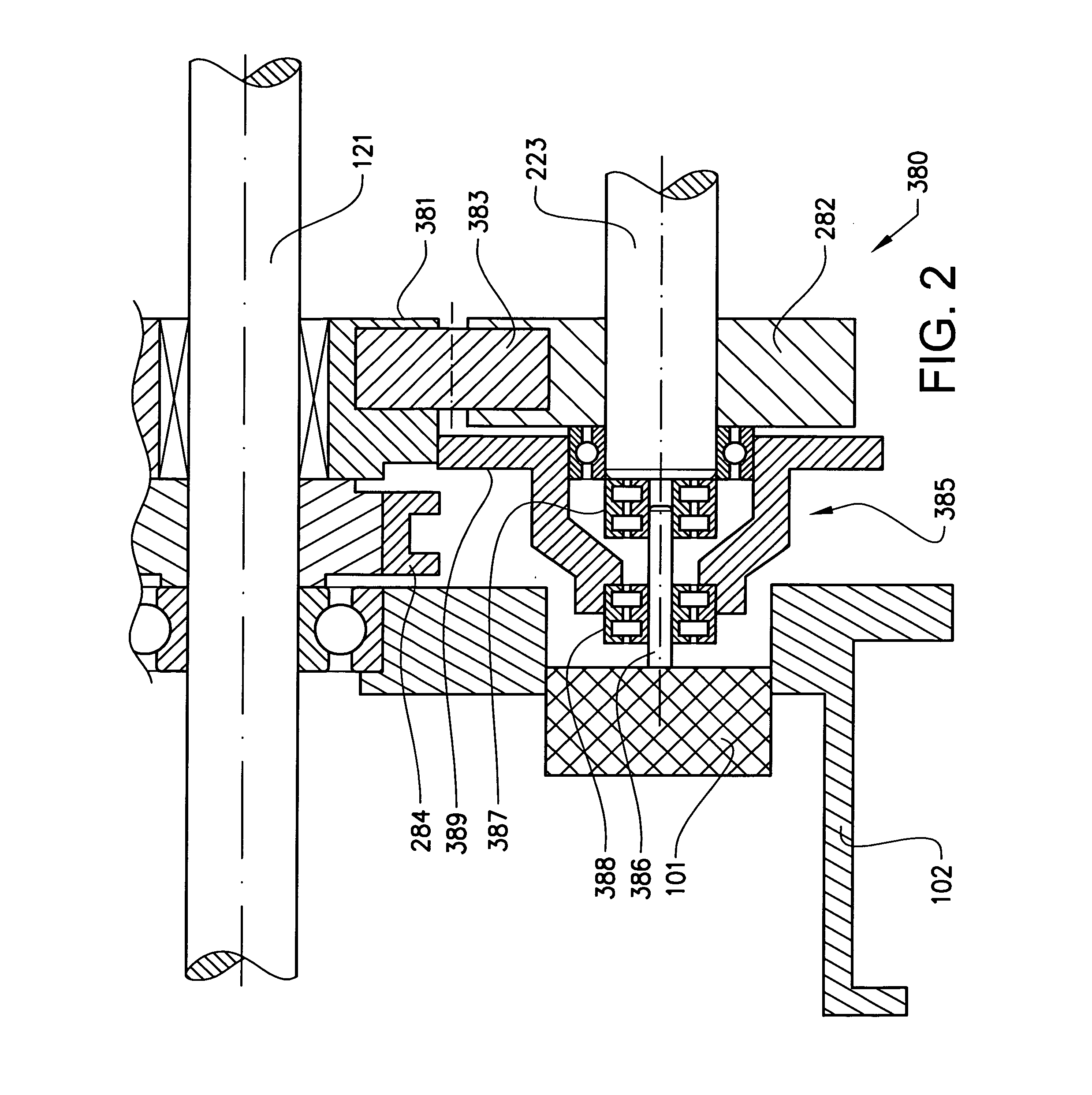
[0027]FIG. 1 shows a transmission 300 according to the invention, having a freewheel mechanism 385 that enables the oil pump 101 to provide oil flow independent of the direction of rotation of the countershaft 223.

[0028]A transmission 300 is arranged inside a housing 102. There are three shafts in the transmission 300; an input shaft 121, a countershaft 223 and a main shaft 124. The input shaft 121 and the main shaft 124 are coaxial, and the countershaft 223 is arranged parallel to them. On the input shaft 121 and the main shaft 124 a number of rotatable, loose gearwheels (381, 130, 132, 134, 136, 138) are arranged. Each of these loose gearwheels (381, 130, 132, 134, 136, 138) are in mesh with a gearwheel (282, 131, 133, 135, 137, 139) that are either fixed on or integral with the countershaft 223.

[0029]The tr...


PUM


Abstract

A transmission includes an input shaft, a main shaft, a countershaft, and an oil pump. The input shaft, the main shaft and the countershaft are provided with gearwheels in order to enable torque transfer in a plurality of forward and backward gear speeds. The oil pump is provided with a freewheel mechanism, which includes an oil pump driveshaft, a first pump drive gearwheel and a first and a second freewheel arranged upon the oil pump driveshaft. Both the first and the second freewheel can transfer torque to the oil pump drive shaft in one and the same direction. The first freewheel is in drive connection with the countershaft and the second freewheel is connected to the first pump drive gearwheel, which meshes with a first gearwheel coaxial with the main shaft and which first gearwheel transfers torque in at least one of the forward or backward gear speeds.

Description

BACKGROUND AND SUMMARY[0001]The present invention relates to field of transmissions and especially to the arrangement of an oil pump in a transmission with a plurality of forward and backward gear speeds.[0002]Especially for heavy road vehicles a large number of forward and backward gear speeds are required. In the reverse gear speeds the direction of rotation of some shafts of the transmission will be opposite to the direction of rotation in the forward gear speeds.[0003]Lubrication of the gears and bearings of the transmission can be facilitated in different ways, by splashing through gearwheels partly submerged in oil or by an oil pump providing a lubrication and cooling flow to bearings and gearwheels distanced from the oil level and not reached by the splashing oil. This flow is normally directed to bearings located high above the oil level and / or not subjected to the splashing flow.[0004]The oil pump is usually located at a low position in the transmission. Thereby, it will be...

Claims


Application Information

Patent Timeline
Patent Type & Authority Applications(United States)
IPC IPC(8): F16H57/04F16H3/091
CPCF16H57/0441F16H3/0915F16H57/0494F16H2200/0043F16H2200/0095Y10T74/19605
Inventor HEDMAN, ANDERSNYLUND, CLAS
Owner VOLVO LASTVAGNAR AB
Why Eureka
Try Eureka