Fish eye lens analyzer

a technology of lens analyzer and fish eye, which is applied in the direction of material analysis, instruments, solid-state devices, etc., can solve the problems of insufficient measurement accuracy, even smaller devices, and spectrometers of the prior art that have not met these needs

Active Publication Date: 2015-06-18
SIEMENS HEALTHCARE DIAGNOSTICS INC
View PDF5 Cites 22 Cited by
  • Summary
  • Abstract
  • Description
  • Claims
  • Application Information

AI Technical Summary

Problems solved by technology

Color comparisons made with the naked eye can lead to imprecise measurement.
Since space is limited, there is a need to make these devices even smaller.
The spectrometers of the prior art have not met these needs.

Method used


Image

  • Fish eye lens analyzer
  • Fish eye lens analyzer
  • Fish eye lens analyzer

Examples


Embodiment Construction

[0028]Throughout this document, the terms “couple” and “coupled” refer to elements which can be directly connected together or one or more intervening elements may also be present. In contrast, the terms “directly couple” and “directly coupled” refer to elements that are directly connected with no intervening elements present.

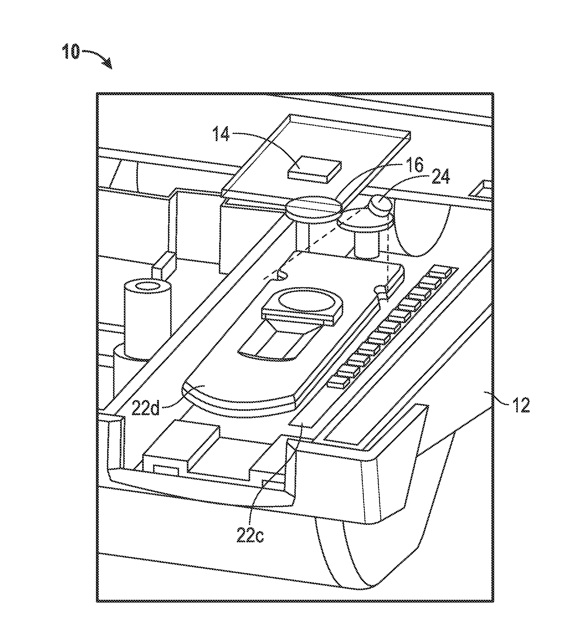
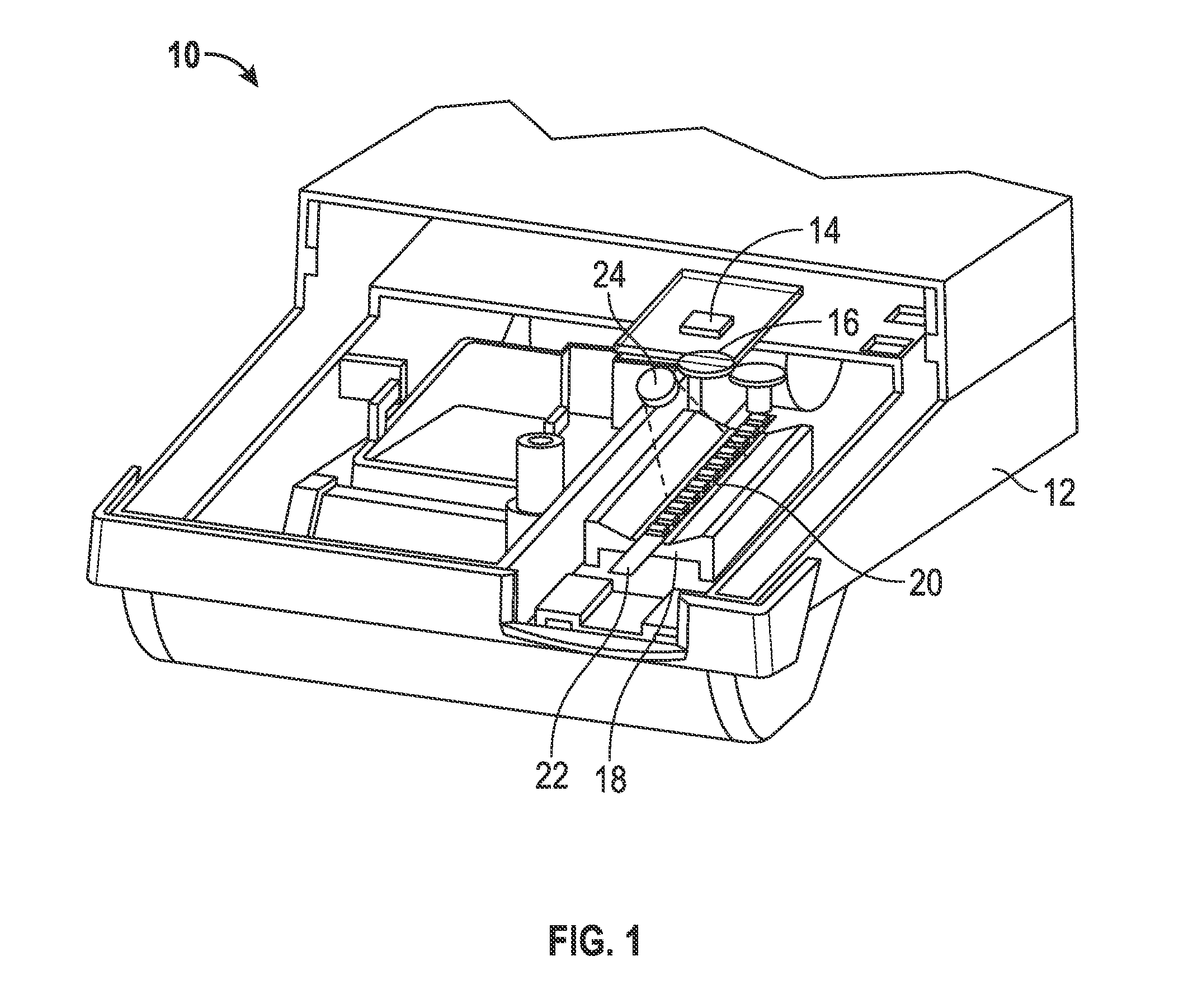
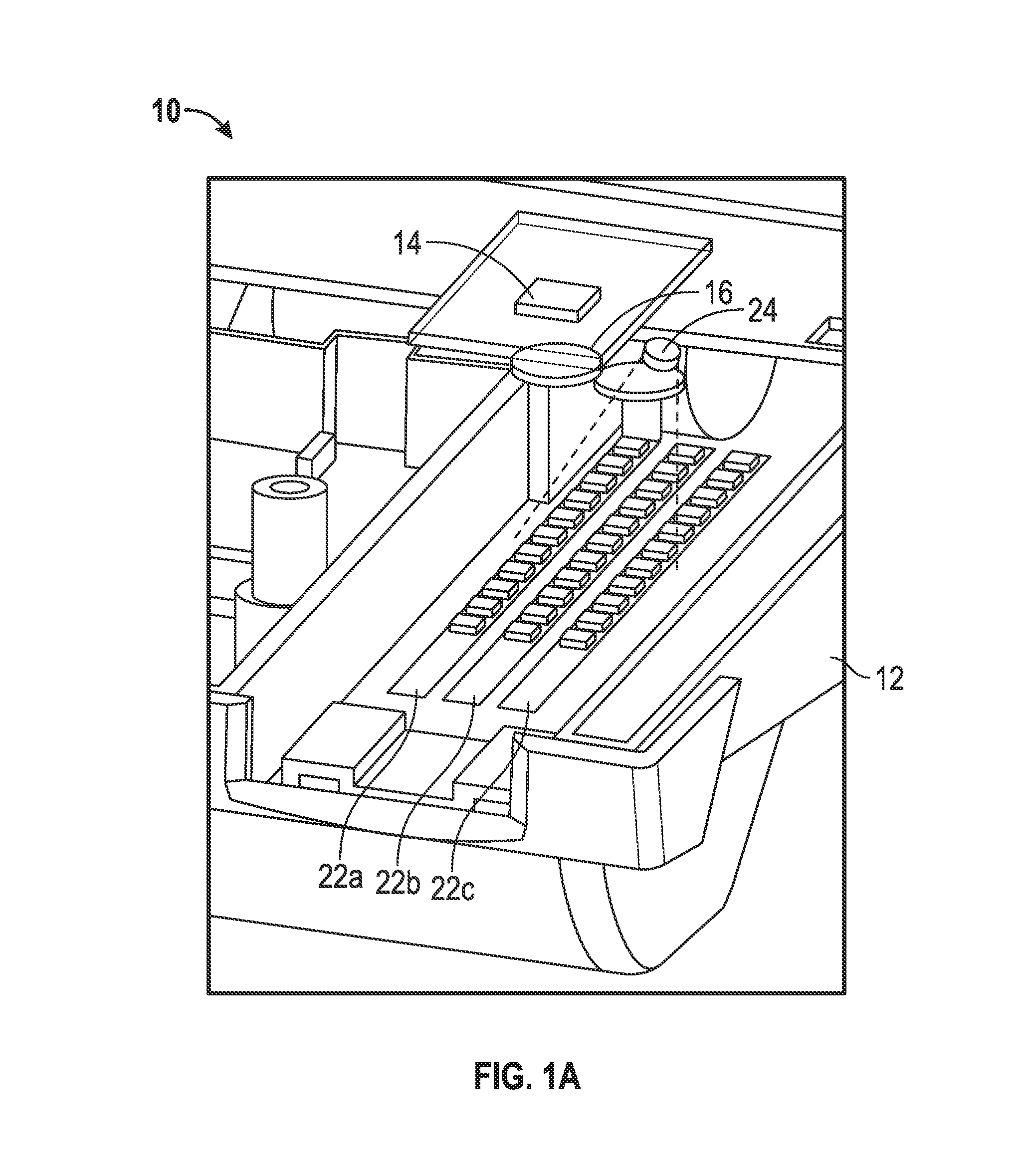
[0029]In one aspect, the disclosure describes an assembly including an imager, a detector capable of capturing image data, and a wide angle lens, often called a fish eye lens. The fisheye lens can be a wide-angle lens that takes in an extremely wide, hemispherical image. For example, the fisheye lens can be a miniature fisheye lens designed for small-format CCD / CMOS imagers. Format sizes may include ¼″ (active area 3.6 mm×2.7 mm), ⅓″ (active area 4.8 mm×3.6 mm) and ½″ (active area 6.6 mm×4.8 mm). The imager can be a camera or other image capture device. Preferably, the imager is a 2D CCD array. The assembly may optionally include a support means for supporting ...


PUM


Abstract

An imaging device is disclosed. The imaging device has a housing, a detector positioned within the housing and has a field of view encompassing one or more target area within the housing to be imaged, a wide-angle lens operatively coupled to the detector, and a support positioned at the target area and configured to receive one or more test component. The wide-angle lens is operatively coupled to the detector such that the detector receives image data of the target area through the wide-angle lens.

Description

[0001]The entirety of U.S. Provisional Application Ser. No. 61 / 648,839, filed on May 18, 2012, is hereby expressly incorporated herein by reference.FIELD OF THE INVENTION[0002]The present invention relates to a readhead for a photometric diagnostic instrument, such as a reflectance spectroscope, for performing tests on a sample of fluid to be analyzed.BACKGROUND OF THE INVENTION[0003]Reagent test strips are widely used in the field of clinical chemistry. A test strip usually has one or more test areas, and each test area is capable of undergoing a color change in response to contact with a liquid specimen. The liquid specimen usually contains one or more constituents or properties of interest. The presence and concentrations of these constituents of interest in the specimen are determinable by an analysis of the color changes undergone by the test strip. Usually, this analysis involves a color comparison between the test area or test pad and a color standard or scale. In this way, r...

Claims


Application Information

Patent Timeline
Patent Type & Authority Applications(United States)
IPC IPC(8): H01L31/0232
CPCH01L31/02325G01N21/8483
Inventor MURRAY, PAUL
Owner SIEMENS HEALTHCARE DIAGNOSTICS INC
Why Eureka
Try Eureka