Optical transmitter and control method of optical transmitter
a control method and optical transmitter technology, applied in electromagnetic transmission, electrical equipment, transmission, etc., can solve the problems of long time and difficulty in determining whether the output light beam of each of the first and second mach-zehnder optical modulators is in the extinction sta
- Summary
- Abstract
- Description
- Claims
- Application Information
AI Technical Summary
Benefits of technology
Problems solved by technology
Method used
Image
Examples
first preferred embodiment
[0019]
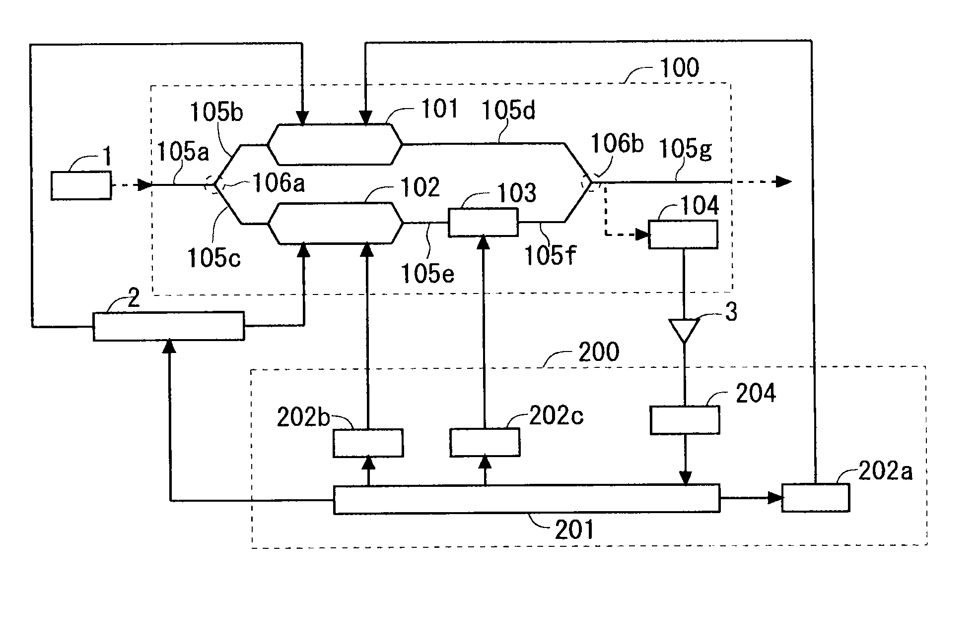
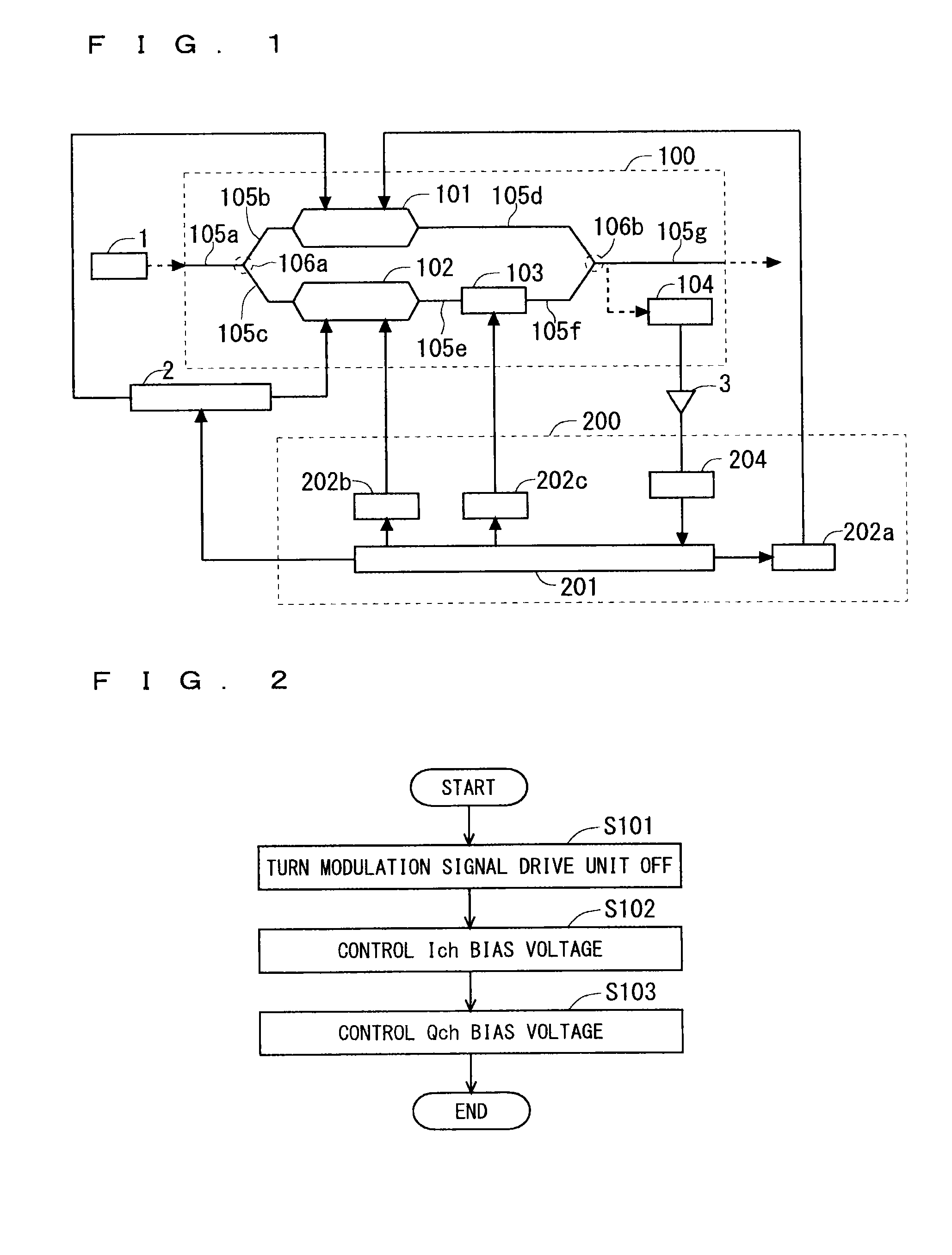
[0020]FIG. 1 is a function block diagram of an optical transmitter according to this preferred embodiment. The optical transmitter according to this preferred embodiment includes an optical modulation unit 100 that modulates a beam incident from a light source 1, based on an input modulation signal and an input bias voltage, a modulation signal drive unit 2 that inputs the modulation signal to the optical modulation unit 100, and a controller 200 that controls operation of the optical modulation unit 100 and the modulation signal drive unit 2. The light source 1 and the optical modulation unit 100 are optically connected by, for example, an optical fiber.
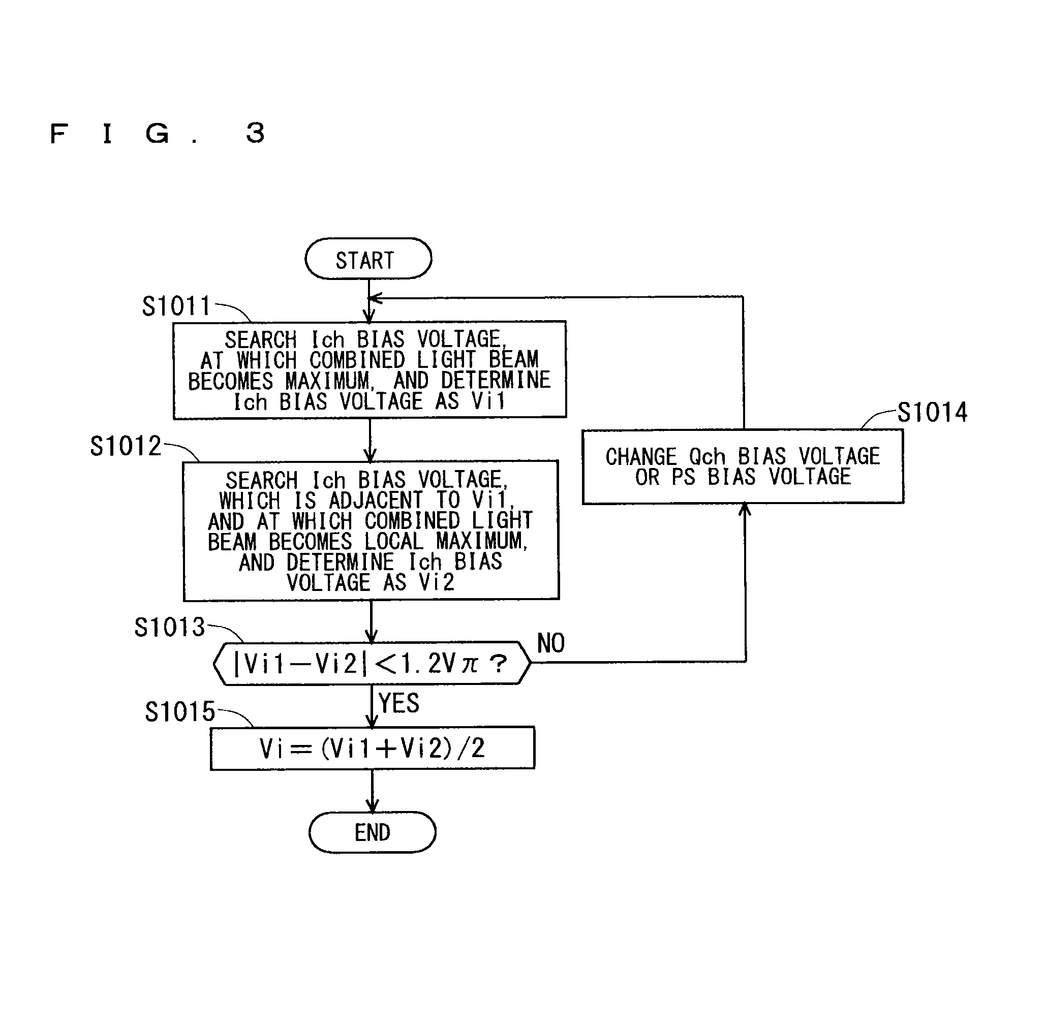
[0021]The optical modulation unit 100 includes a first optical modulator 101, a second optical modulator 102, and an optical phase regulator 103. The first and second optical modulators 101 and 102, and the optical phase regulator 103 are formed in a substrate containing, for example, lithium niobate. Additionally, on the subs...
second preferred embodiment
[0065]
[0066]The optical transmitter according to the first preferred embodiment monitors the output of the optical modulation unit 100 in an initial state where no modulation signal is input to the optical modulation unit 100, and searches the initial bias voltages of the first and second optical modulators 101 and 102 such that the light beam output from the optical modulation unit 100 is brought into the most extinction state. An optical transmitter according to this preferred embodiment searches initial values (initial bias voltages Vi and Vq) of an Ich bias voltage and a Qch bias voltage such that a light beam output from an optical modulation unit 100 is brought into the most extinction state, in an initial state where no modulation signal is input to the optical modulation unit 100, similarly to the first preferred embodiment.
[0067]FIG. 6 is a function block diagram of the optical transmitter according to this preferred embodiment. The optical transmitter according to this pre...
third preferred embodiment
[0077]
[0078]The optical transmitter according to each of the first preferred embodiment and the second preferred embodiment monitors the output of the optical modulation unit 100 in an initial state where no modulation signal is input to the optical modulation unit 100, and searches the initial bias voltages Vi and Vq of the first and second optical modulators 101 and 102 such that the light beam output from the optical modulation unit 100 is brought into the most extinction state.
[0079]An optical transmitter according to this preferred embodiment searches initial bias voltages Vi and Vq such that a light beam output from an optical modulation unit 100 is brought into the most extinction state, in an initial state where no modulation signal is input to the optical modulation unit 100, similarly to the first preferred embodiment and the second preferred embodiment. This preferred embodiment is different from the first preferred embodiment and the second preferred embodiment in that a...
PUM
 Abstract
Description
Claims
Application Information
 - R&D
- Intellectual Property
- Life Sciences
- Materials
- Tech Scout
- Unparalleled Data Quality
- Higher Quality Content
- 60% Fewer Hallucinations
Browse by: Latest US Patents, China's latest patents, Technical Efficacy Thesaurus, Application Domain, Technology Topic, Popular Technical Reports.
© 2025 PatSnap. All rights reserved.Legal|Privacy policy|Modern Slavery Act Transparency Statement|Sitemap|About US| Contact US: help@patsnap.com


