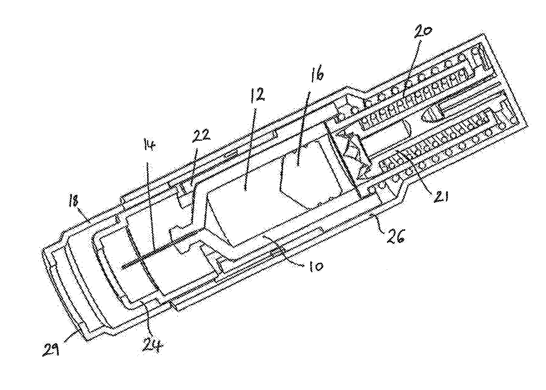
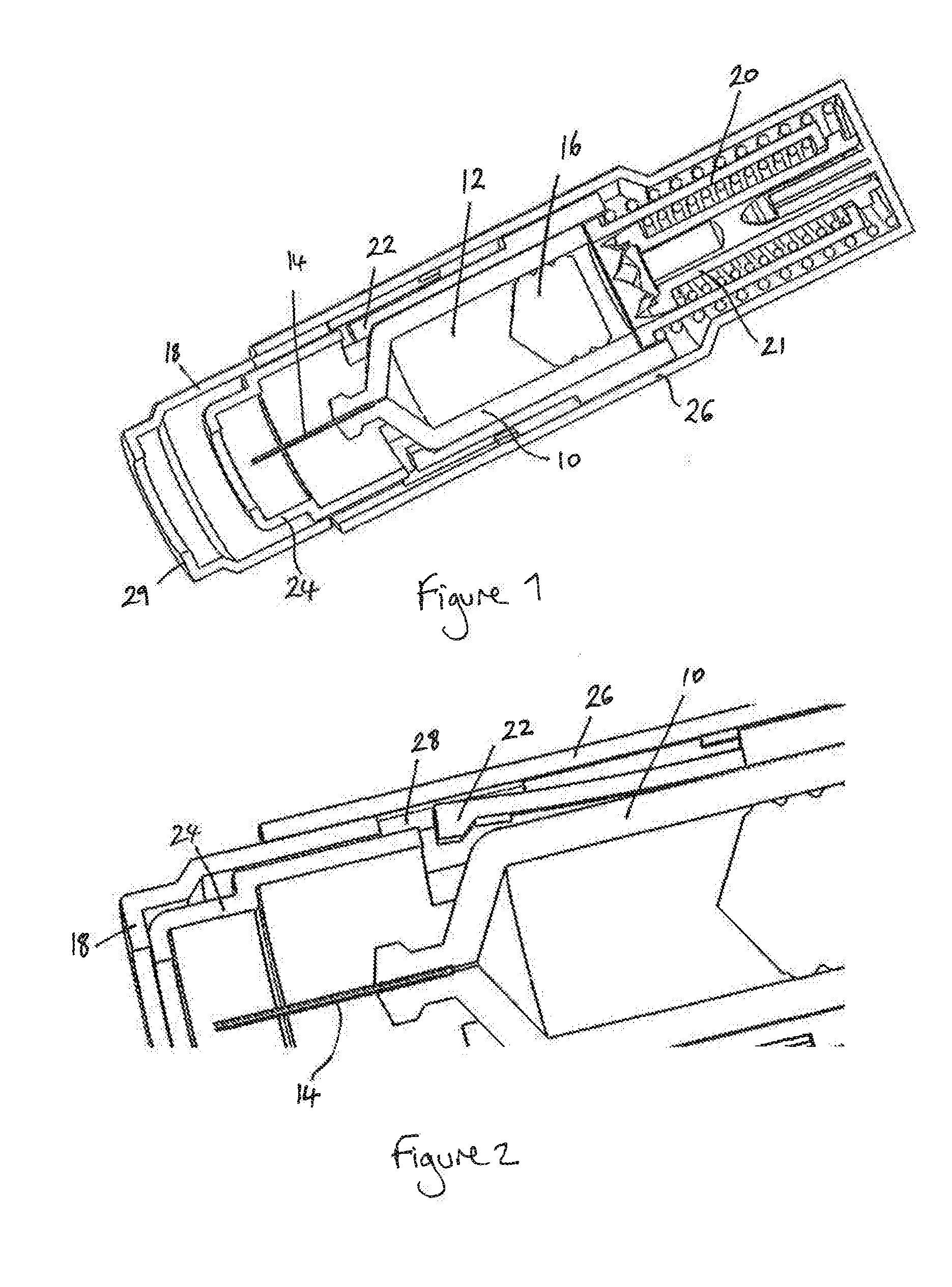
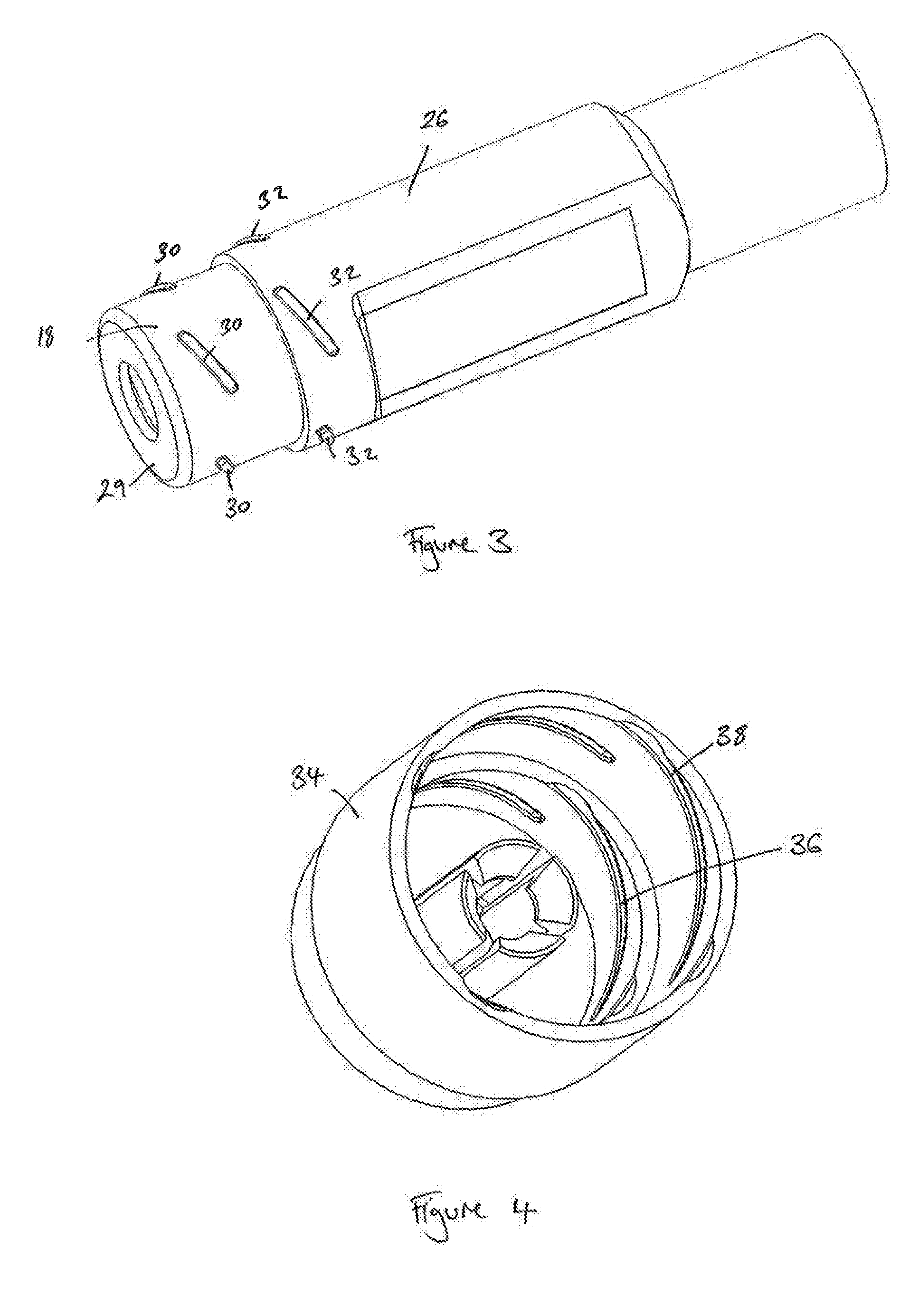
Injector device with mechanism for preventing accidental activation
a technology of injector device and mechanism, which is applied in the direction of intravenous device, infusion needle, infusion syringe, etc., can solve the problem that the delivery mechanism cannot be operated after operation
- Summary
- Abstract
- Description
- Claims
- Application Information
AI Technical Summary
Benefits of technology
Problems solved by technology
Method used
Image
Examples
third embodiment
[0077]FIG. 10 is a perspective, cross-sectional view of the invention. FIG. 10 shows the front end of an autoinjector of the type shown in FIG. 1, with a cap 34 and needle shield 40. In the embodiment of FIG. 10, the cap 34 includes flexible portions 70 which extend into an aperture formed in the activation member 18, and thereby prevent inward movement of the activation member to the activation position.
[0078]FIG. 11 shows the embodiment of FIG. 10 with the cap and needle shield removed. The housing 26 includes an enlarged portion 72 which defines a passageway through which the flexible portions 70 on the cap can pass and flex inwardly to engage a window in the activation member 18. To remove the cap 34, the cap is simply pulled off in a direction parallel to the axis of the needle 14. The cap may include a plurality of spaced apart flexible portions 70, spaced around the circumference of the cap or may include a single flexible portion. The cap and flexible portions can be formed ...
fourth embodiment
[0079]FIG. 12 is a perspective view of the front end of an autoinjector in accordance with the invention. In the embodiment of FIG. 12, the outer housing 26 includes a window portion 82, into which a flexible portion of the cap 34 is received. The flexible portion of the cap in the window portion 82 engages a protrusion 80 on the activation member 18 to prevent movement of the activation member 18 into an activation position. FIGS. 13 and 14 are cross-sectional views of the embodiment of FIG. 12, illustrating the engagement of the cap 34 with the window 82. In order to facilitate removal of the cap, the housing includes cam surfaces 84 formed adjacent the window 82 that engage with the corresponding cam surfaces 86 on the interior surface of the cap. As the cap is pulled away from the housing, cam surfaces 84 engage with cam surface 86 and slide past one another, thereby urging the flexible portion of the cap 88 out of engagement with aperture 82 and past protrusion 80 formed on the...
fifth embodiment
[0080]FIG. 15 is a cross-section through a front end of an autoinjector in accordance with the invention. In the embodiment of FIG. 15 the activation member 18 is prevented from moving to the activation position by an intermediate component 100, coupled to the cap 34. The intermediate component is positioned substantially within an interior of the activation member 18. Movement of the activation member towards the activation position results in the front face of the activation member 18 abutting the intermediate component 100, which is itself constrained from movement by abutment with interior housing 24 and by latching element 110.
[0081]FIG. 16 is a perspective view of the intermediate component 100. As shown in FIG. 16, the intermediate component comprises a ring structure 102, from which four resilient, U-shaped legs 104 extend. The intermediate component 100 may be formed from any suitable resilient material, such as spring steel or a moulded plastic such as polypropylene, and m...
PUM
 Abstract
Description
Claims
Application Information
 - R&D
- Intellectual Property
- Life Sciences
- Materials
- Tech Scout
- Unparalleled Data Quality
- Higher Quality Content
- 60% Fewer Hallucinations
Browse by: Latest US Patents, China's latest patents, Technical Efficacy Thesaurus, Application Domain, Technology Topic, Popular Technical Reports.
© 2025 PatSnap. All rights reserved.Legal|Privacy policy|Modern Slavery Act Transparency Statement|Sitemap|About US| Contact US: help@patsnap.com


