Head Drive Unit And Inkjet Printer

a technology of inkjet printer and drive unit, which is applied in the direction of printing, other printing apparatus, etc., can solve problems such as failure of discharge, and achieve the effects of preventing an increase in and increasing the viscosity of ink

Inactive Publication Date: 2015-06-25
KONICA MINOLTA INC
View PDF1 Cites 3 Cited by
  • Summary
  • Abstract
  • Description
  • Claims
  • Application Information

AI Technical Summary

Benefits of technology

[0010]Thus, it is an object of the present invention is to provide a head drive unit that enables applying a meniscus oscillation signal and preventing an increase in viscosity of an ink in a nozzle even when an inkjet head is present outside an image forming region of a recording medium where a print timing signal is not acquired, and to provide an inkjet printer including this head drive unit.
[0011]Further, the discharge failure problem caused due to an increase in viscosity of the ink can be avoided by forcedly continuously discharging droplets from the nozzles. However, in this case, since the print timing signal cannot be acquired when the inkjet head is present outside the image forming region, a signal used for forcedly discharging the droplets (which will be referred to as a flushing signal hereinafter) cannot be applied to the inkjet head, and there is the same problem as that in case of the meniscus oscillation signal.
[0012]Therefore, it is another object of the present invention to provide a head drive unit that enables preventing an increase in viscosity of an ink in a nozzle by forcedly discharge a droplet from the nozzle even when an inkjet head is present outside an image forming region of a recording medium where a print timing signal cannot be acquired, and to provide an inkjet printer including this head drive unit.
[0013]Furthermore, it is still another object of the present invention to provide a head drive unit that enables preventing an increase in viscosity of an ink in a nozzle by selecting either application of a meniscus oscillation signal or forced discharge of a droplet from the nozzle even when an inkjet head is present outside an image forming region of a recording medium where a print timing signal cannot be acquired, and to provide an inkjet printer including this head drive unit.

Problems solved by technology

In an inkjet printer that forms an image by impacting minute droplets from nozzles onto a recording medium, viscosity of an ink in the nozzles is increased when discharge of the droplets is stopped for a small period of time alone, thereby leading to a discharge failure in some situations.

Method used


Image

  • Head Drive Unit And Inkjet Printer
  • Head Drive Unit And Inkjet Printer
  • Head Drive Unit And Inkjet Printer

Examples


Embodiment Construction

[0059]Embodiments according to the present invention will now be described with reference to the drawings.

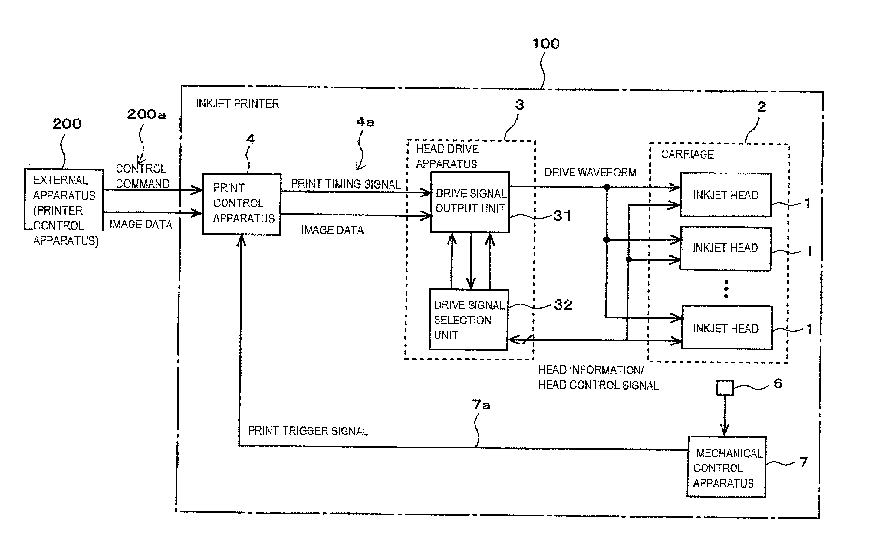
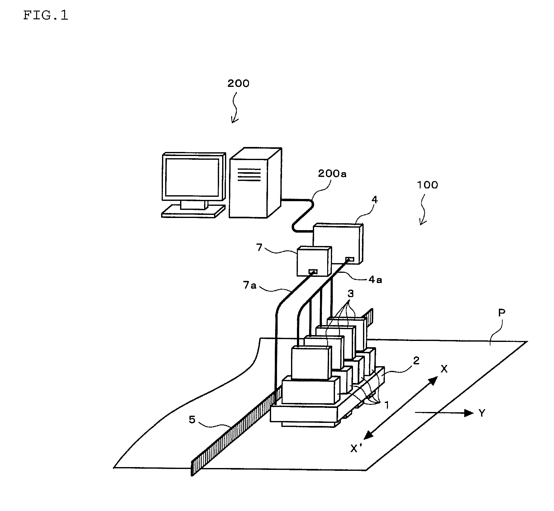
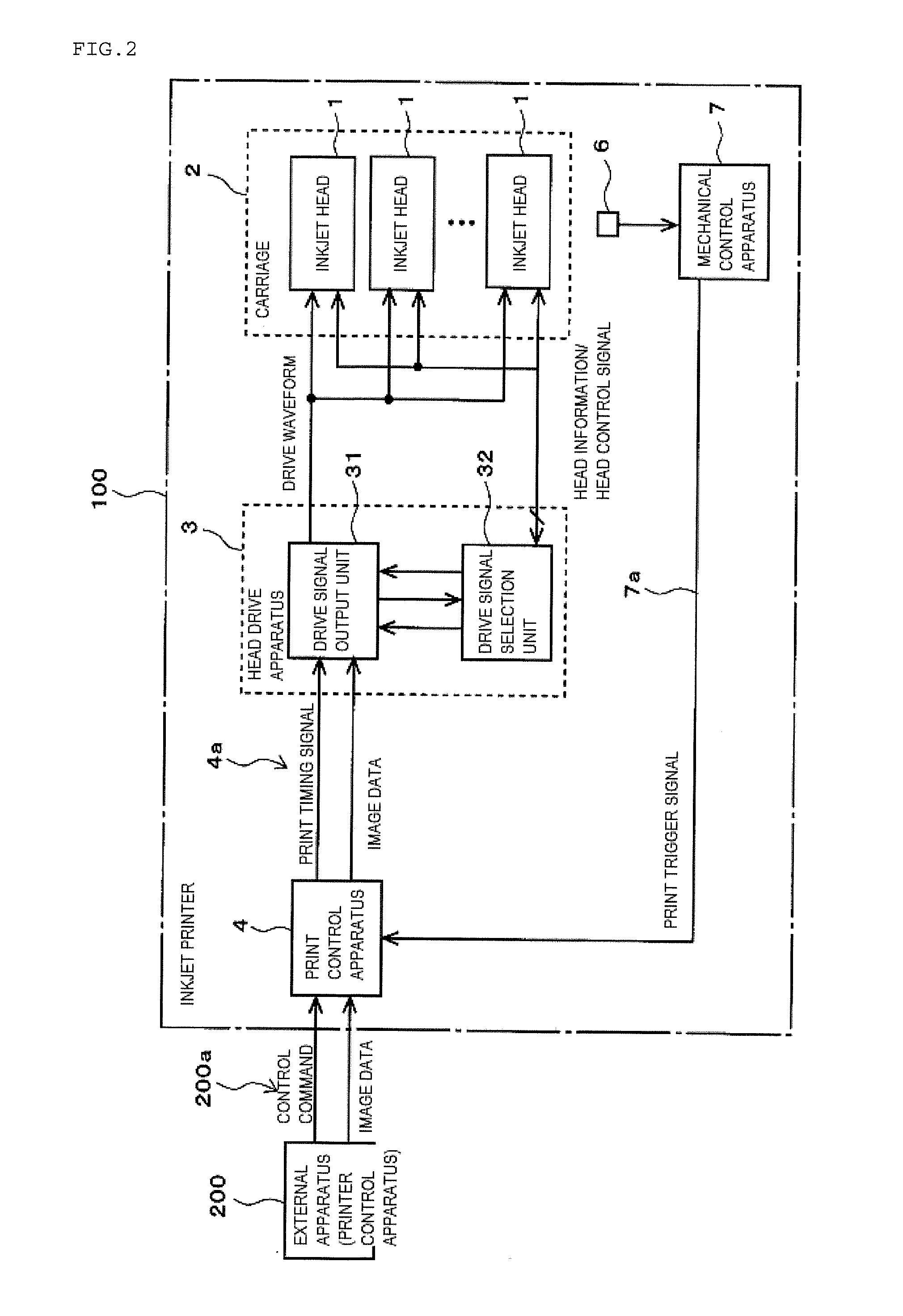
[0060]FIG. 1 is an overall structural view showing an example of an inkjet system including an inkjet printer, and FIG. 2 is a structural block diagram thereof.

[0061]In the drawings, reference numeral 100 denotes an inkjet printer, and 200 designates a printer control apparatus that is an external apparatus configured to control the entire inkjet printer 100.

[0062]In the inkjet printer 100, reference numeral 1 denotes each inkjet head (which will be simply referred to as a head hereinafter), and the inkjet heads 1 are mounted on a common carriage 2 in such a manner that nozzle surfaces having nozzles that discharge inks aligned thereon face the lower side in the drawing. Here, four heads that discharge inks in different colors are exemplified. However, the number of the heads 1 does not really matter. The carriage 2 is provided to be reciprocable along a main scanning direction ...


PUM


Abstract

An object is to provide a head drive unit that prevents an increase in viscosity of inks in nozzles even when a head is present outside an image forming region and also provide an inkjet printer, and the head drive unit includes: a drive signal output device 31 that outputs either a discharge signal or a meniscus oscillation signal to each head; a cycle generator 326 that generates a cyclic oscillation timing signal for the meniscus oscillation signal; an input interruption detector 324 that detects that input of a print timing signal is interrupted; and a drive signal selector 32 that selects the meniscus oscillation signal as a drive signal output from the drive signal output device and continuously applies the meniscus oscillation signal to all nozzles of each head in synchronization with an oscillation timing signal when interruption of the input of the print timing signal is detected.

Description

TECHNICAL FIELD [0001]The present invention relates to a head drive unit and an inkjet printer, and more particularly to a head drive unit and an inkjet printer that can prevent an increase in viscosity of an ink even when an inkjet head is present outside an image forming region for a recording medium.BACKGROUND [0002]In an inkjet printer that forms an image by impacting minute droplets from nozzles onto a recording medium, viscosity of an ink in the nozzles is increased when discharge of the droplets is stopped for a small period of time alone, thereby leading to a discharge failure in some situations.[0003]In an actual printing operation, there are some nozzles that keep preventing discharge of droplets depending on image data. In the prior art, a meniscus oscillation signal used for oscillating a liquid surface at a nozzle tip (which will be referred to as a meniscus hereinafter) is uniformly input to all nozzles before or after a discharge signal that is output to an inkjet hea...

Claims


Application Information

Patent Timeline
Patent Type & Authority Applications(United States)
IPC IPC(8): B41J2/045
CPCB41J2/04581B41J2/04573B41J2/01B41J2/0458B41J2/04588B41J2/04596B41J2/16526B41J2/175
Inventor KOMADA, NAOYATSUBOTANI, SHINGO
Owner KONICA MINOLTA INC
Why Eureka
Try Eureka