
Printing device and printing method

a printing device and printing method technology, applied in printing, duplicating/marking methods, other printing apparatus, etc., can solve problems such as overheating state, risk of ignition, and ejection failure, and achieve the effects of increasing the viscosity of ink, preventing the increase of the temperature of the medium, and efficient heating within a short tim

Active Publication Date: 2019-01-24
MIMAKI ENG
View PDF4 Cites 0 Cited by
  • Summary
  • Abstract
  • Description
  • Claims
  • Application Information

AI Technical Summary

Benefits of technology

The patent describes a method of drying ink on a medium by using heating modules. However, existing methods have limitations such as ejection failure and safety concerns. The patent proposes a method using a near infrared lamp to heat the ink without heating the ink-jet head or the medium. This method improves drying efficiency and prevents safety issues. Additionally, the patent suggests a method using multiple ink-jet heads and energy irradiation modules to appropriately increase the viscosity of the ink before ejection. This results in better printing performance without excessive temperature increase.

Problems solved by technology

However, in a case of performing heating at such a high temperature, when the medium is stopped being conveyed due to some troubles, the medium is caused to be in an overheating state, and there may be a risk of ignition and the like.
As a result, nozzle clogging and the like may be caused, and a problem of ejection failure may be generated.
On the other hand, in a case of performing heating at a high heating temperature as described above, it takes some time to raise or reduce the temperature.
In this case, a size of the device unavoidably has to be increased by extending a line distance, for example.
As a result, a problem such as an ejection failure is easily caused.
However, in this case, for example, dust particles (for example, paper dust) generated from the medium and surrounding dust may approach or touch the near infrared lamp to cause a fire in some cases.
When paper dust, dust, ink, vapor generated from the ink, and the like adhere to a surface of the lamp, heat radiation energy amount of the lamp is lowered, and drying efficiency of the ink on the medium is deteriorated in some cases.
In this case, for example, a problem is caused such that required electric power is significantly large.
In this case, burns and ignition of the medium due to overheating, or ejection failure of a nozzle in the ink-jet head may be more likely to be caused.
As a result, upsizing of the device and significant increase of cost, for example, would become major problems.
In a case of performing heating at a high temperature using the method as described above, it takes much time to raise the temperature to a set heating temperature, for example, which may cause a problem of lowered productivity.

Method used


Image

  • Printing device and printing method
  • Printing device and printing method
  • Printing device and printing method

Examples


Embodiment Construction

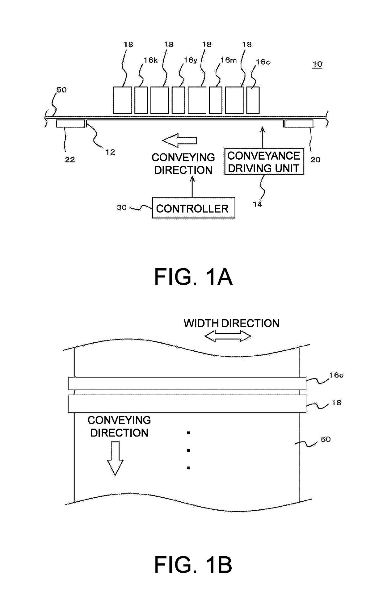
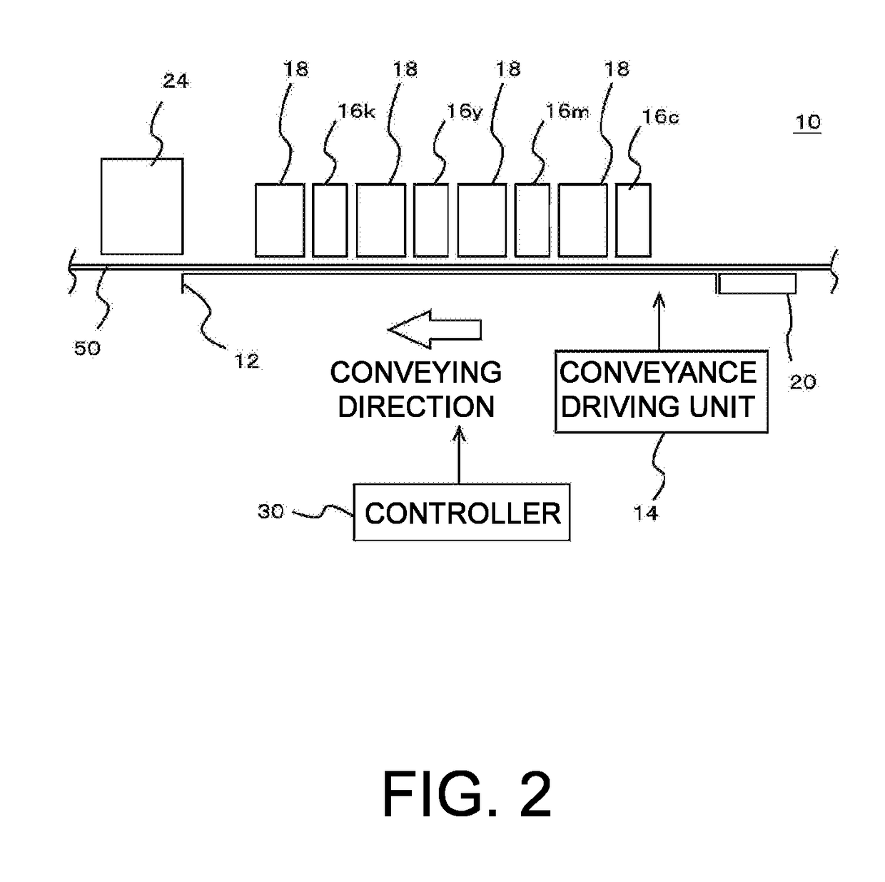
[0030]The following describes an embodiment according to the disclosure with reference to the drawings. FIG. 1A and FIG. 1B illustrate an example of a printing device 10 according to the embodiment of the disclosure. FIG. 1A is a side view illustrating a configuration example of a principal part of the printing device 10. FIG. 1B is a top view illustrating part of the printing device 10. In this example, the printing device 10 is an ink-jet printer of a line system, and includes a stage 12, a conveyance driving unit 14, a plurality of ink-jet heads 16c to 16k, a plurality of ultraviolet ray irradiation units 18, a preheater 20, an after heater 22, and a controller 30.

[0031]Except the points described below, the printing device 10 may have a characteristic that is the same as or similar to that of a known printing device. For example, in addition to the configuration described above and described below, the printing device 10 may further have various configurations that are the same ...


PUM

PropertyMeasurementUnit
temperatureaaaaaaaaaa

Abstract

To dry ink using a more appropriate method in a case of performing printing using an ink-jet printer of a line system and the like. A printing device that performs printing using an ink-jet system includes: a conveyance driving unit as a conveyance module that conveys a medium; ink-jet heads; and an ultraviolet ray irradiation unit as an energy irradiation module. A length of the ink-jet heads in a width direction of the medium is larger than a width of a region to be printed. Ink ejected from the ink-jet heads is ink that contains an energy ray absorber and a solvent, the ink being fixed to the medium by evaporating the solvent. The ultraviolet ray irradiation unit irradiates the ink adhering onto the medium with ultraviolet rays to volatilize and remove at least part of the solvent contained in the ink.

Description

CROSS REFERENCE TO RELATED APPLICATIONS[0001]This application claims the priority benefit of Japanese Patent Application No. 2017-138762, filed on Jul. 18, 2017. The entirety of the above-mentioned patent application is hereby incorporated by reference herein and made a part of this specification.BACKGROUND OF THE DISCLOSURETechnical Field[0002]The disclosure relates to a printing device and a printing method.Background Art[0003]In recent years, ink-jet printers are used in various fields. In the related art, as a configuration of the ink-jet printer, there is known a configuration of a line system (configuration of an ink-jet line printer) that performs printing on a medium conveyed by using an ink-jet head (line head) the length of which in a width direction of a medium (recording medium) is longer than that of a region to be printed on the medium (for example, refer to Patent Literature 1). As ink for an ink-jet printer, in the related art, widely used is evaporation drying type ...

Claims


Application Information

Patent Timeline
Patent Type & Authority Applications(United States)
IPC IPC(8): B41J11/00B41M5/00
CPCB41J11/002B41M5/0011B41M5/0023B41M7/0081B41M7/009B41J11/00214B41J11/00244
Inventor OTSUKA, TOSHIYAOHNISHI, MASARU
Owner MIMAKI ENG
Learn More