High resolution eddy current array probe

a technology of eddy current array and high resolution, which is applied in the direction of hysteresis curve measurement, magnetic measurement, instruments, etc., can solve the problems of not being sensitive enough to small flaws, modifying the electrical impedance of the coil, and modifying the electrical voltage produced by the receive coil

Inactive Publication Date: 2015-06-25
EDDYFI NDT INC
View PDF8 Cites 24 Cited by
  • Summary
  • Abstract
  • Description
  • Claims
  • Application Information

AI Technical Summary

Problems solved by technology

Defects in the material (cracks, pitting, wall loss, or other discontinuities) disrupt the flow of the eddy current and its magnetic field, thus also modifying the electrical impedance of the coil.
Defects in the material disrupt the flow of the eddy current and its magnetic field, thus also modifying the electrical voltage produced by the receive coil.
Furthermore, if the coil size is too small or too large, it will not be sensitive enough to small flaws.
Most of the time, it is not possible to combine the optimized transmit to receive coil distance, the optimal circular coil diameter and reach a high coil density in an array of coils without having to distribute the array of coil on several adjacent rows.
The resulting probe design is either a low resolution design compromised with reduced performances or a good resolution probe with several rows of coils.
The additional rows of coil necessitate an encoding mechanism to realign the signal from each row to build a single image and elongate the probe length which can create mechanical compatibility issues in several applications.

Method used


Image

  • High resolution eddy current array probe
  • High resolution eddy current array probe
  • High resolution eddy current array probe

Examples


Embodiment Construction

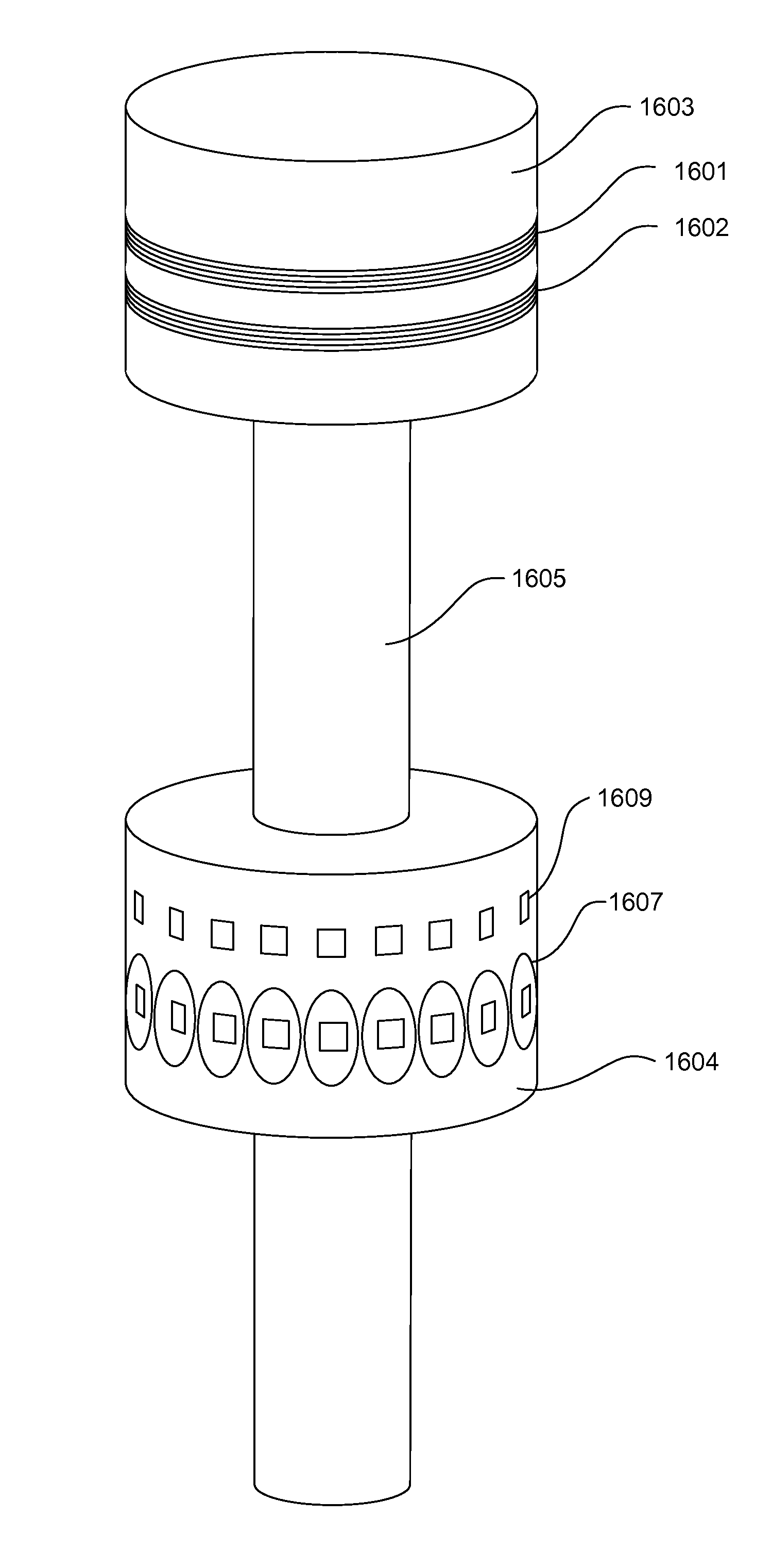
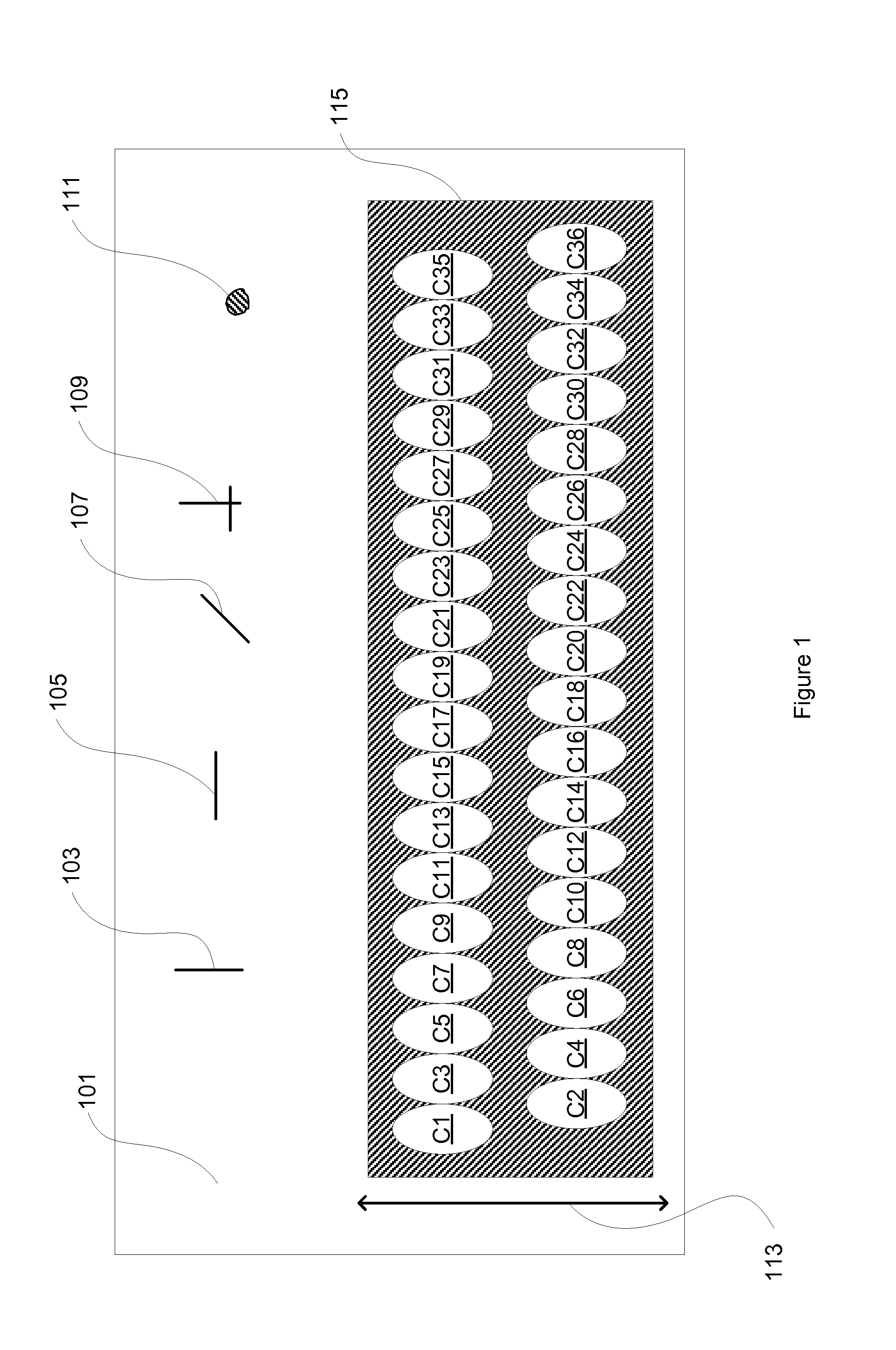
[0050]The eddy current array probe comprises a probe body having a surface. The probe body is adapted to be displaced along a scan direction. The array probe also includes a plurality of coils arranged in a linear configuration on the surface and at least one conductor extending from the probe body. Each coil is connected to a conductor and a common return path.

[0051]The coils are adapted to be operated in one mode among a transmit mode, an inactive mode and a receive mode at each of a plurality of time-spaced instances. At least two adjacent coils of the plurality are adapted to be operated in the inactive mode between a coil adapted to be in transmit mode and a coil adapted to be in receive mode in the linear configuration.

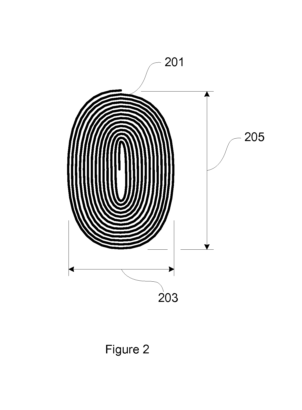
[0052]In one embodiment, the coils have an elongated shape and are referred to as high density coils. The longitudinal dimension of the elongated shape can be at an angle to a longitudinal dimension of the linear configuration. In one embodiment, that elongated ...


PUM

PropertyMeasurementUnit
aspect ratioaaaaaaaaaa
thicknessaaaaaaaaaa
diameteraaaaaaaaaa

Abstract

An eddy current array probe comprising a probe body adapted to be displaced along a scan direction; a plurality of coils arranged in a linear configuration on the surface of the probe body, the coils being adapted to be operated in one mode among a transmit mode, an inactive mode and a receive mode at each of a plurality of time-spaced instances, at least two adjacent coils of the plurality being adapted to be operated in the inactive mode between a coil adapted to be in transmit mode and a coil adapted to be in receive mode in the linear configuration at each of the time-spaced instances; at least one conductor extending from the probe body; each coil of the plurality being connected to one of the at least one conductor and a common return path. In one embodiment, the coils have an elongated shape.

Description

TECHNICAL FIELD[0001]The invention relates to eddy current testing and more particularly to an eddy current testing probe using an array of coils in transmit-receive mode.BACKGROUND OF THE ART[0002]Eddy Current Technology (ECT) is based on the physics phenomenon of electromagnetic induction: an alternating current flowing through a coil instantly generates an oscillating magnetic field. If the coil and its magnetic field approach an electrically conductive material, a circular flow of electrons, known as eddy current, is induced in this electrically conductive material. In turn, this eddy current generates its own magnetic field, which will interact through mutual inductance with the coil and its magnetic field. Defects in the material (cracks, pitting, wall loss, or other discontinuities) disrupt the flow of the eddy current and its magnetic field, thus also modifying the electrical impedance of the coil.[0003]Some basic ECT probes have a single coil which is used both as a driver ...

Claims


Application Information

Patent Timeline
Patent Type & Authority Applications(United States)
IPC IPC(8): G01N27/90G01R33/09G01R33/07
CPCG01N27/9033G01N27/904G01R33/09G01R33/07G01N27/9013G01N27/9006
Inventor HARDY, FLORIANGRENIER, MARC
Owner EDDYFI NDT INC
Why Eureka
Try Eureka